
Straight knife manufacturing method

a manufacturing method and straight knife technology, applied in the direction of manufacturing tools, manufacturing equipment/tools, incision instruments, etc., can solve the problems of easy bending of austenitic stainless steel knives, difficult use of knives, and easy bending of blades, so as to improve sharpness, easy control, and improve the effect of precision formation

Inactive Publication Date: 2016-10-27
MATSUTANI SEISAKUSHO CO LTD
View PDF4 Cites 0 Cited by
  • Summary
  • Abstract
  • Description
  • Claims
  • Application Information

AI Technical Summary

Benefits of technology

The present invention provides a straight knife made of austenitic stainless steel that can increase strength of a thin and sharp blade tip portion, is strong against deformation, and can prevent decrease in sharpness. The blade tip is rounded through electrolytic polishing or chemical polishing, making it difficult to bend, and using austenitic stainless steel reduces the risk of rusting. The sharpness of the knife decreases when the blade tip is rounded, but electrolytic polishing or chemical polishing improves sharpness by removing burrs and bending. The straight knife is used for cutting by thrusting the blade tip into an object, such as sclera, and the technician's perception of sharpness during use is not affected even if the blade tip is rounded. The knife is designed in a way that the angle of gradient of the edge to the tissue is small, improving sharpness and making it user-friendly.

Problems solved by technology

As a result, there is a problem that when forming an incision in a cornea, a sclera, or the like during ophthalmic surgery, the blade tip 1f of the austenitic stainless steel knife is easily bent. FIG. 5D is a diagram illustrating peripheral parts of the same blade tip 1f (referred to as ‘blade tip portion’ hereafter) as in FIG. 5C, illustrating a bent state due to elasticity when cutting a cornea, a sclera, or the like.
If the blade tip portion easily bends, it is difficult to use as a knife.
Moreover, there is a problem that if deformation is great, it does not return to its original shape and cannot be used as a knife thereafter.

Method used


Image

  • Straight knife manufacturing method
  • Straight knife manufacturing method
  • Straight knife manufacturing method

Examples


Embodiment Construction

[0030]An embodiment of the present invention is described while referencing the attached drawings.

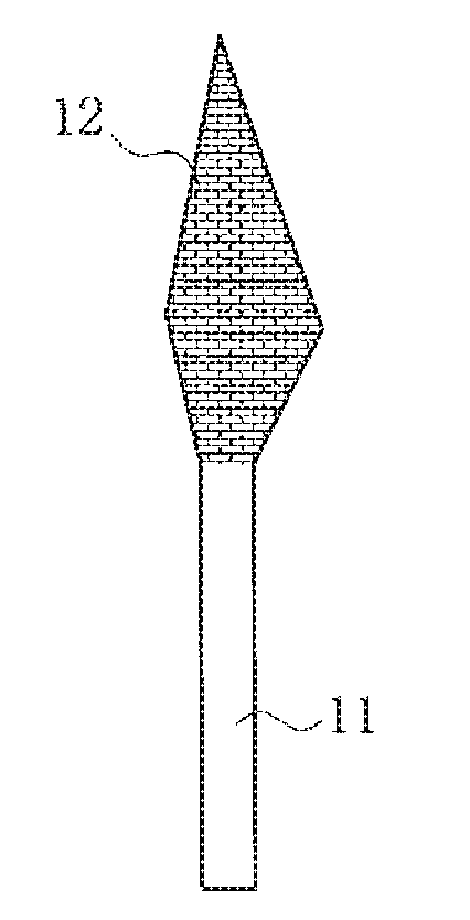
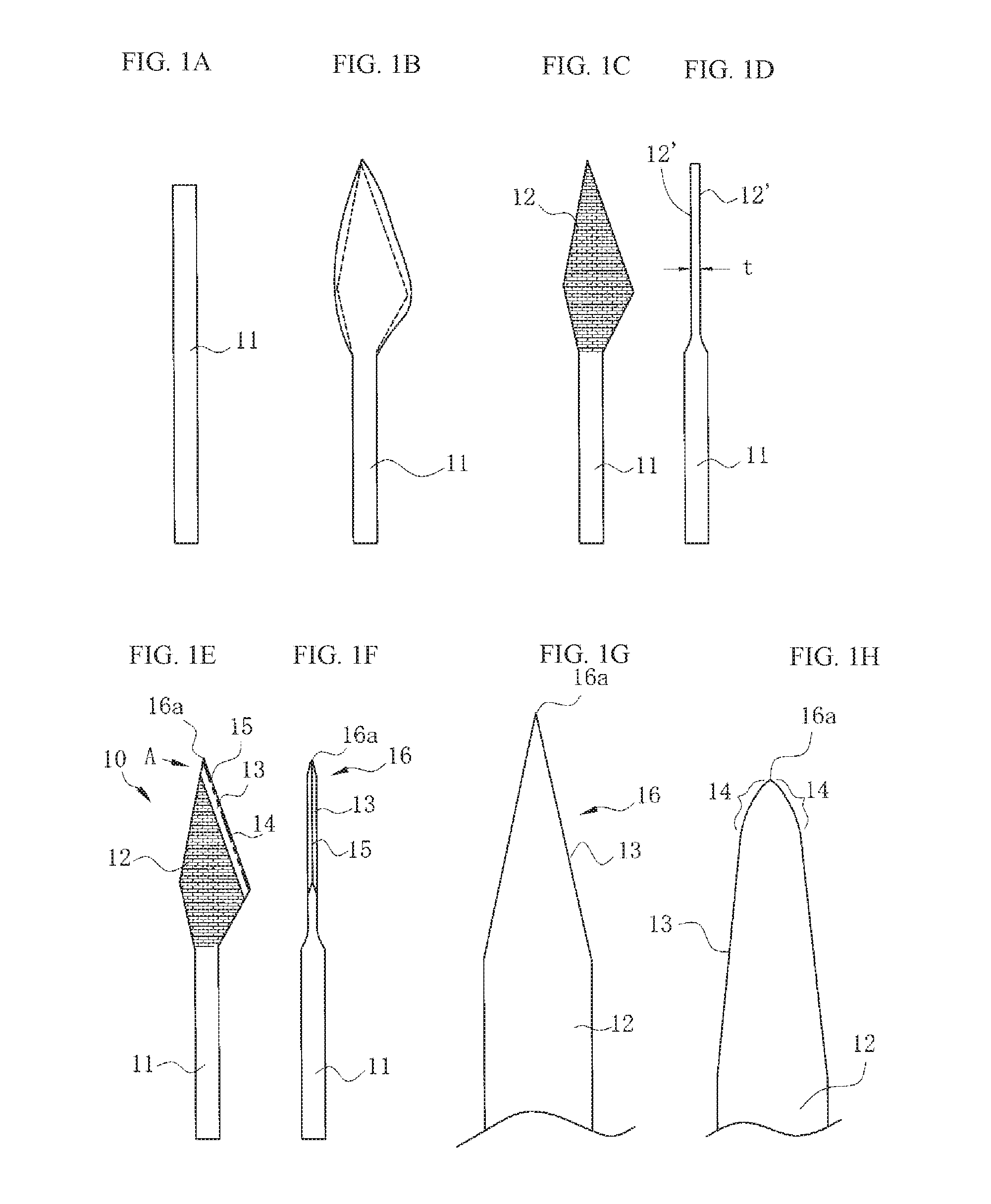
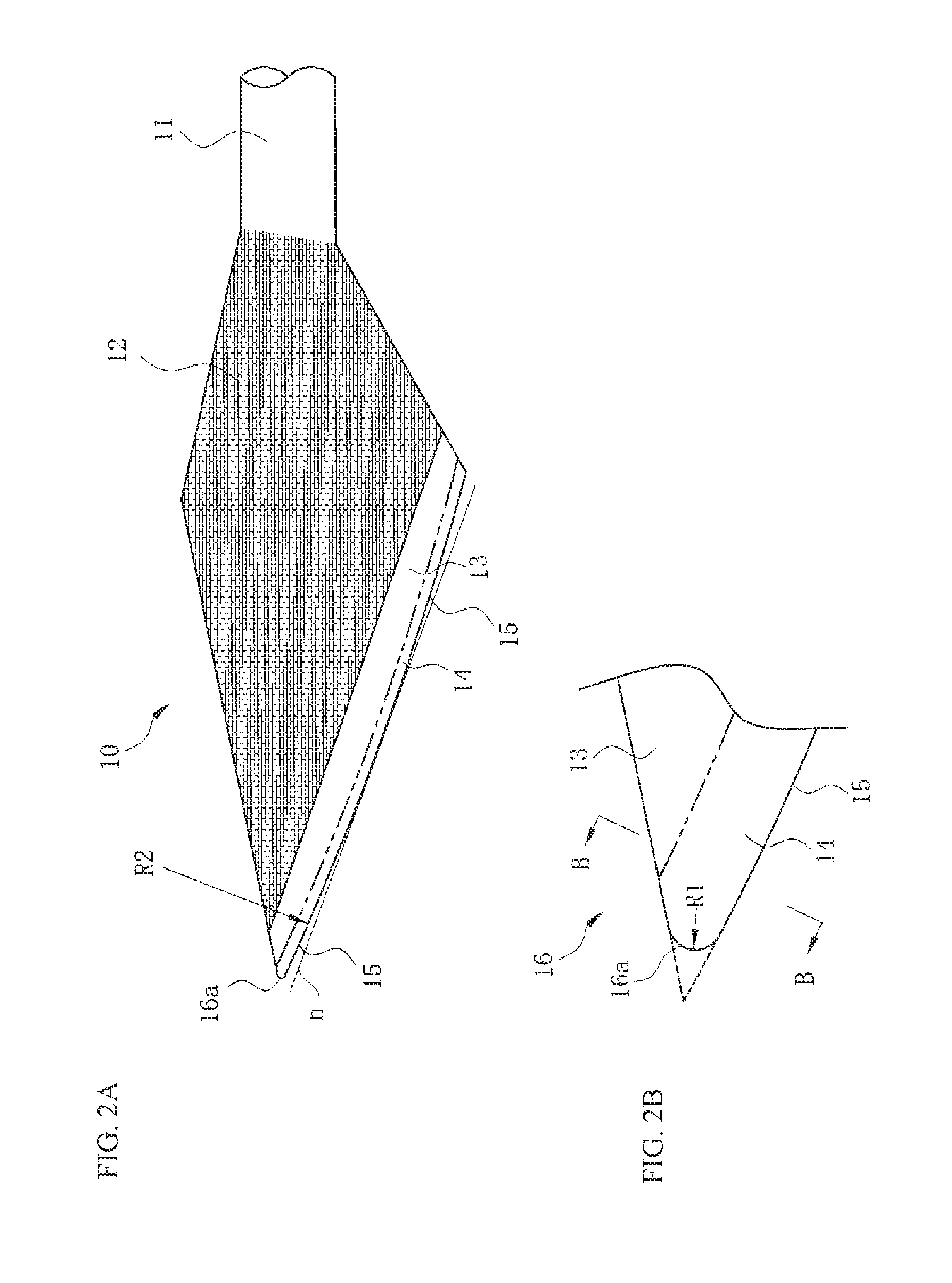
[0031]FIGS. 1A to 1F are diagrams describing a manufacturing method for a straight knife 10 according to the present invention. To begin with, a raw, round bar 11 is cut at a predetermined length shown in FIG. 1A. This is made from an austenitic stainless steel round bar having a fibrous crystalline structure. Then, as shown in FIG. 1B, the front end side is flattened by a press, and excessive portions indicated by dotted lines are cut in a subsequent pressing step so as to have a planar pointed end, thereby forming an approximately rhombus cutting portion 12 viewed in the top view. As shown in FIGS. 1C and 1D, both flattened surfaces 12′ are polished and made into smooth surfaces and made into a predetermined thickness t. The flattened surfaces 12′ of the cutting portion 12 are then made into irregular reflection surfaces through blasting. Making irregular reflection surfaces keeps the...


PUM

PropertyMeasurementUnit
widthaaaaaaaaaa
thicknessaaaaaaaaaa
shapeaaaaaaaaaa

Abstract

A method of manufacturing a straight knife includes pressing one end of a rounded austenitic stainless steel rod flat and press-cutting away an excess portion of the flattened end to form a blade; grinding the blade to form a slanted surface and an edge along at least a portion of the periphery of the blade; removing burrs along the slanted surface and the edge of the blade by electrolytic polishing or chemical polishing; and continuing with the electrolytic polishing or chemical polishing to form, at a tip of the slanted surface, a cutting portion of the blade having a cross-sectional shape defined by convex curves.

Description

CROSS-REFERENCE TO RELATED APPLICATION[0001]This application is a continuation under 35 U.S.C. §120 of prior U.S. application Ser. No. 13 / 818,989, filed on Feb. 26, 2013 and currently pending, which is a National Stage entry under 35 U.S.0 371(c) of International Application No. PCT / JP2011 / 069389, filed on Aug. 29, 2011, which in turn claims priority to Japanese Application No. 2010-192068, filed on Aug. 30, 2010, the entire disclosures of which are incorporated herein by reference.TECHNICAL FIELD[0002]The present invention relates to a method of manufacturing a medical straight knife used in surgery, such as a straight ophthalmic knife, an LRI knife for astigmatism correction, and the like.BACKGROUND ART[0003]The straight knife and the LRI knife used for ophthalmic surgery have a thin, sharp front end and a straight cutting edge several millimeters long extending from the end. When using them, mainly the front end and a cutting edge portion approximately 1 mm from the front end are...

Claims


Application Information

Patent Timeline
Patent Type & Authority Applications(United States)
IPC IPC(8): B23P15/28C25F3/24A61F9/013C23F3/00B24B3/60A61B17/3211
CPCB23P15/28B24B3/605A61B17/3211A61B2017/00526C23F3/00C25F3/24A61F9/0133
Inventor SAITO, MASAHIKO
Owner MATSUTANI SEISAKUSHO CO LTD
Learn More