Corrugated-core flanges for spools and reels

a technology of corrugated core and spools, applied in the field of corrugated core flanges for spools and reels, can solve the problems of inability to implement all engineering principles available in manufacturing techniques, failure to inherently resist fracture of flanges from impact loads, and spools and reels suffering from lack of intelligent application of technology

Inactive Publication Date: 2005-04-05
SONOCO DEV INC
View PDF71 Cites 16 Cited by
  • Summary
  • Abstract
  • Description
  • Claims
  • Application Information

AI Technical Summary

Benefits of technology

In view of the foregoing, it is a primary object of the present invention to provide spools and reels and a method of designing them that will optimize strength, stiffness, fracture, distortion, toughness, and so forth at various locations within the flanges for survival of drop tests.
Thus, for example, outer portions of a flange may be permitted to crush, bend, break, and so forth in order absorb certain loads. The rim having greater circumference, more material may be naturally provided for absorbing such damage. Meanwhile, a hub may be configured to minimize damage, since a hub may be substantially smaller than a rim (outer diameter or outermost portion) of a flange. In one presently preferred embodiment, bending loads may selectively fracture corrugation walls on one axial side, while transferring loads away to other areas. This re-distribution may reduce fractured circumference at the core, maintaining integrity while permitting fracturing of adequate length to absorb shock loads.

Problems solved by technology

Spools and reels have suffered from a lack of intelligent application of technology for many years.
Nevertheless, manufacturing techniques continue to fall short of implementing all of the principles of engineering that are available.
Likewise, due to the conventional shapes of central tubes (hubs, cores, etc.), the junctions with flanges are not inherently resistant to fracture from impact loads caused by dropping.
Otherwise, a substantial length of stranded material may be damaged beyond use.
The collection and recycling of spools is hardly worth the effort, considering that their materials are not easily recyclable.
Fracture may damage wire, preclude removal, or release the wire in a tangled, useless mass.
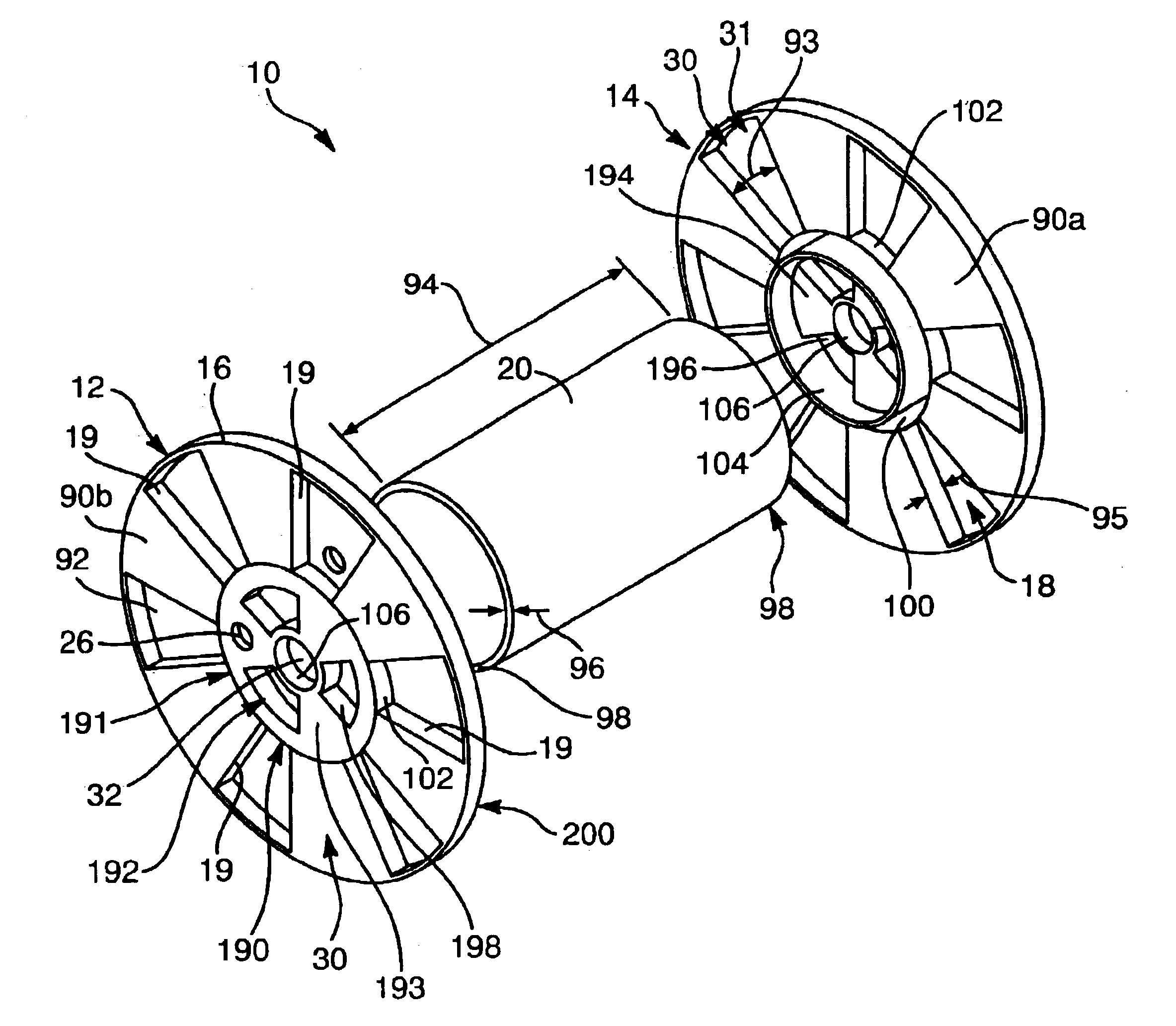
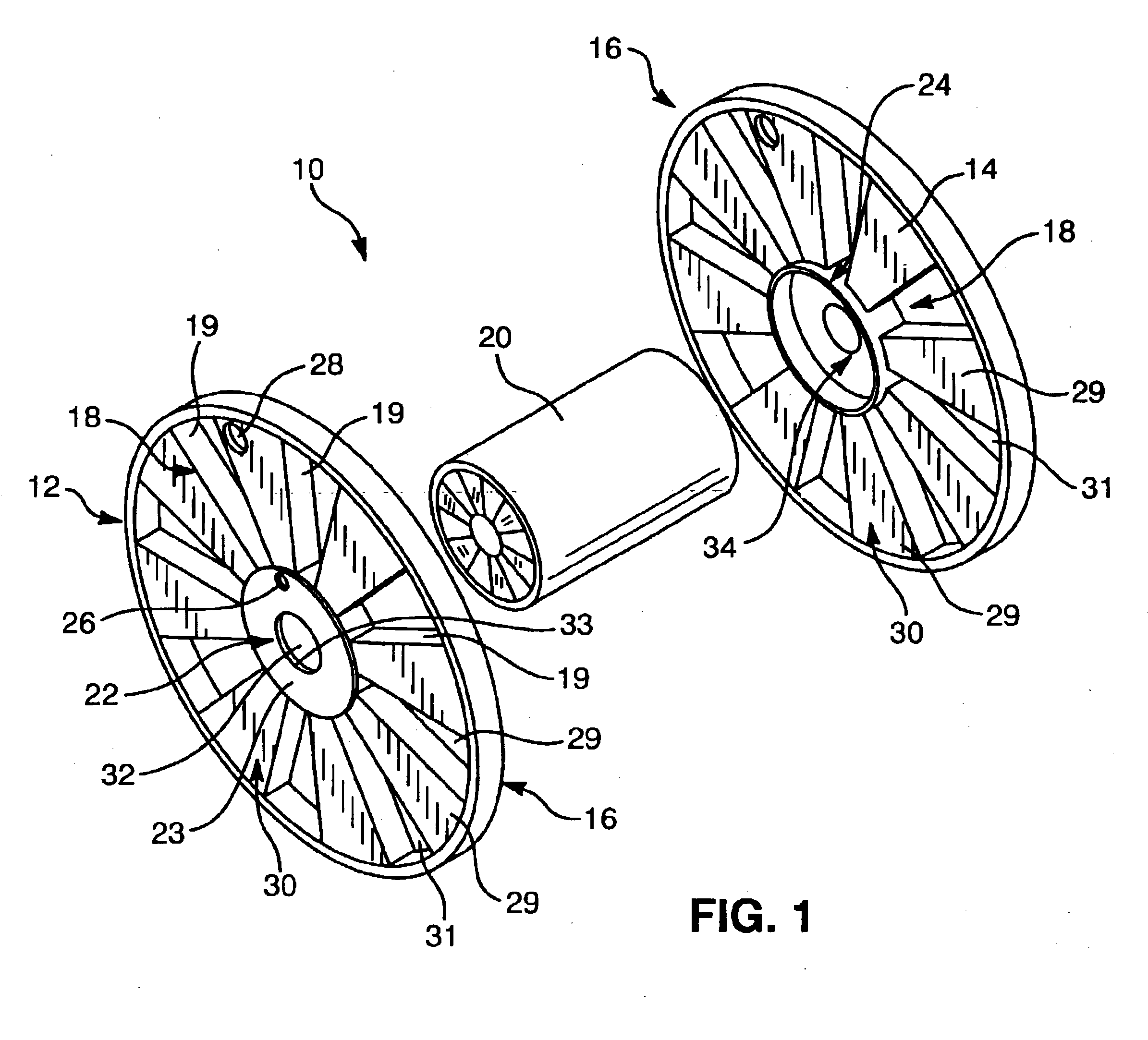
Spools may break at the corner where the tube portion meets the flange portion or may fracture at an engagement portion along the tube portion.
Spools and reels experience significant breakage during drop tests when manufactured in styrene or styrene-based plastics such as ABS.
Tough means that a material can tolerate a relatively large amount of straining or stretching before rupture.
As a result, when a reel of wire is dropped, the energy of impact breaks the spool.
Nevertheless, olefinic plastics are not typical in the art of wire spools.
However, lack of a solvent is one problem, lack of a durable adhesive is another.
The inventory management problem created by unique spools of various sizes is untenable, although the cost of some olefinic resins is lower than that of styrene-based resins.
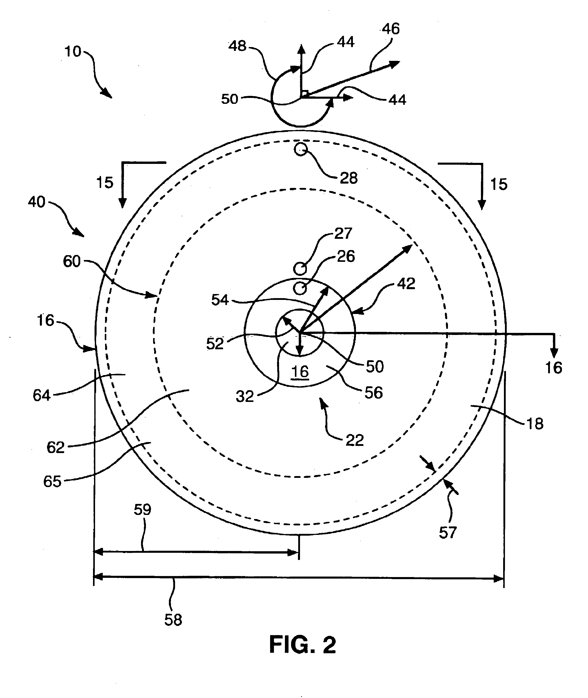
The designs available use wall thicknesses which result in warpage as well.
All these factors, as well as others, combine to leave olefinic resins, and bonded parts made therefrom, largely unused in the spool industry.
In a radial drop, spools that break typically fail near the middle of the length of the tube.
Plastic spools of 12-inch diameter and greater are rare and tend to be very complex.
Inexpensive plastics are not sufficiently strong or tough to tolerate even ordinary use with such a large mass of wire or cable wrapped around the spool.
Moreover, large flanges for reels are very difficult to manufacture.
Likewise, the additional manufacturing cost of large spools is problematic.
Therefore, the flanges have very slow cooling times and molding machines have low productivity in producing them.
That is, once styrene has been injection molded, the mechanical properties of the resulting plastic are degraded.
Thus, if a spool is recycled, ground up into chunks or beads and re-extruded as part of another batch, the degradation in quality can be substantial.
The reels have an additional difficulty when they are dropped during use.
The tube is prone to slip with respect to the flanges, breaking, tilting or otherwise losing its integrity under excessive loads.
For the largest reels, rolling over or into obstacles or from decks during handling is more likely to be the cause of damage.
A splinter or blemish in a reel can damage insulation on new cable or wire wrapped therearound at the manufacturing plant.
Damaged insulation destroys much of the value of a reel of cable or wire.
That is, the wire must be spliced, or may have damage extending over several wrapped layers of wire.
Splices segmenting the original length of wire wrapped on the reel add costs in labor, reliability, service and the like.
Wood cannot be recycled and reconstructed cost effectively.
The reels do not effectively burn without the labor investment of this dismantling operation.
Also, a wooden reel that is slightly out of adjustment, damaged, or broken, is problematic.
A broken reel leaves a large area splintered to damage wire insulation.
Also, steel is heavy, subject to damage by the environment such as by stains, rust, peeling of paint, denting, accumulation of coatings or creation of small burrs on surfaces and corners.
For example, when a reel is rolled over a hard surface, sharp objects, grit or rocks tend to raise small burrs on the outer edge of the flange.
As with wooden reels, only to a greater extent, a burr on a steel reel tends to act like a knife, slicing through insulation and ruining wire.
Perhaps the most difficult aspect of burrs is that they are hardly detectable at sizes which are nevertheless highly damaging to insulation.
Of course the weight and cost of steel reels is another factor in the difficulty of employing them for delivery of cable.
Catastrophic failure of reels and spools limits their applicability within the wire and cable industry.
The risk of losing the use of the stranded material held thereon is not to be risked for the cost of using plastic spools and reels.

Method used


Image

  • Corrugated-core flanges for spools and reels
  • Corrugated-core flanges for spools and reels
  • Corrugated-core flanges for spools and reels

Examples


Embodiment Construction

It will be readily understood that the components of the present invention, as generally described and illustrated in the Figures herein, could be arranged and designed in a wide variety of different configurations. Thus, the following more detailed description of the embodiments of the apparatus and methods of the present invention is not intended to limit the scope thereof. Rather, the scope of the invention is as broad as claimed herein. The illustrations merely represent certain, presently preferred embodiments of the invention. Embodiments of the invention will be best understood by reference to the drawings, wherein like parts are designated by like numerals throughout.

Those of ordinary skill in the art will, of course, appreciate that various modifications to the details of the apparatus and methods illustrated in the Figures may easily be made without departing from the essential characteristics of the invention. Thus, the following description of the Figures is by way of ex...


PUM

PropertyMeasurementUnit
diameteraaaaaaaaaa
diameteraaaaaaaaaa
diameteraaaaaaaaaa

Abstract

A flange design providing improved strength, fracture resistance, and the like using corrugations extending substantially radially from an arbor aperture toward a rim portion. A spool or reel may include a tubular member to receive a stranded material wrapped therearound. A first flange comprising a core portion and an outer portion may secure to one end of the first flange engaging the tubular member. A second flange may secure to the other end of the tubular member. The core portion of a flange may comprise an arbor wall defining the perimeter of an arbor aperture. The arbor wall may be directly contacted and supported by a plurality of corrugations extending radially therefrom. The outer portion of a flange may contact the core portion and extending radially away therefrom to an outer edge to restrain the stranded material in an axial direction.

Description

BACKGROUND1. The Field of the InventionThis invention relates to spools and reels for receiving stranded materials, and, more particularly, to novel systems and methods for producing plastic flanges for reels and spools as take-up of electrical wire during manufacture.2. The Background ArtSpools and reels have suffered from a lack of intelligent application of technology for many years. Spools date back hundreds if not thousands of years. Wooden spools and reels have been used in the textile industry as well as various electrical industries for many years with almost no innovation in their structures. Some use of plastic materials began a few decades ago. Nevertheless, manufacturing techniques continue to fall short of implementing all of the principles of engineering that are available.Manufacturing techniques tend to focus on the simplicity of manufacture, and the simplicity of design, rather than the optimization of strength, weight, stiffness, non-catastrophic failure modes, and...

Claims


Application Information

Patent Timeline
Patent Type & Authority Patents(United States)
IPC IPC(8): B65H75/04B65H75/14B65H75/18
CPCB65H75/18B65H75/14B65H2701/51524B65H2701/5112Y10T29/49826B65H2701/5136Y10T29/4998
Inventor RIPPLINGER, C. ROBERT
Owner SONOCO DEV INC
Why Eureka
Try Eureka