Electric actuator

Inactive Publication Date: 2005-04-19
SMC CORP
View PDF6 Cites 18 Cited by
  • Summary
  • Abstract
  • Description
  • Claims
  • Application Information

AI Technical Summary

Benefits of technology

[0008]A general object of the present invention is to provide an electric actuator which appropriately absorbs the load appl

Problems solved by technology

However, in the conventional electric actuator, when a heavy workpiece is placed on the slide table to transport the workpiece, the linear guide mechanism cannot absorb the load applied by the action of the gravity exerted on the workpiece in a circumferential direction about the center of the axis of the feed screw shaft, in a circu

Method used


Image

  • Electric actuator
  • Electric actuator
  • Electric actuator

Examples


Embodiment Construction

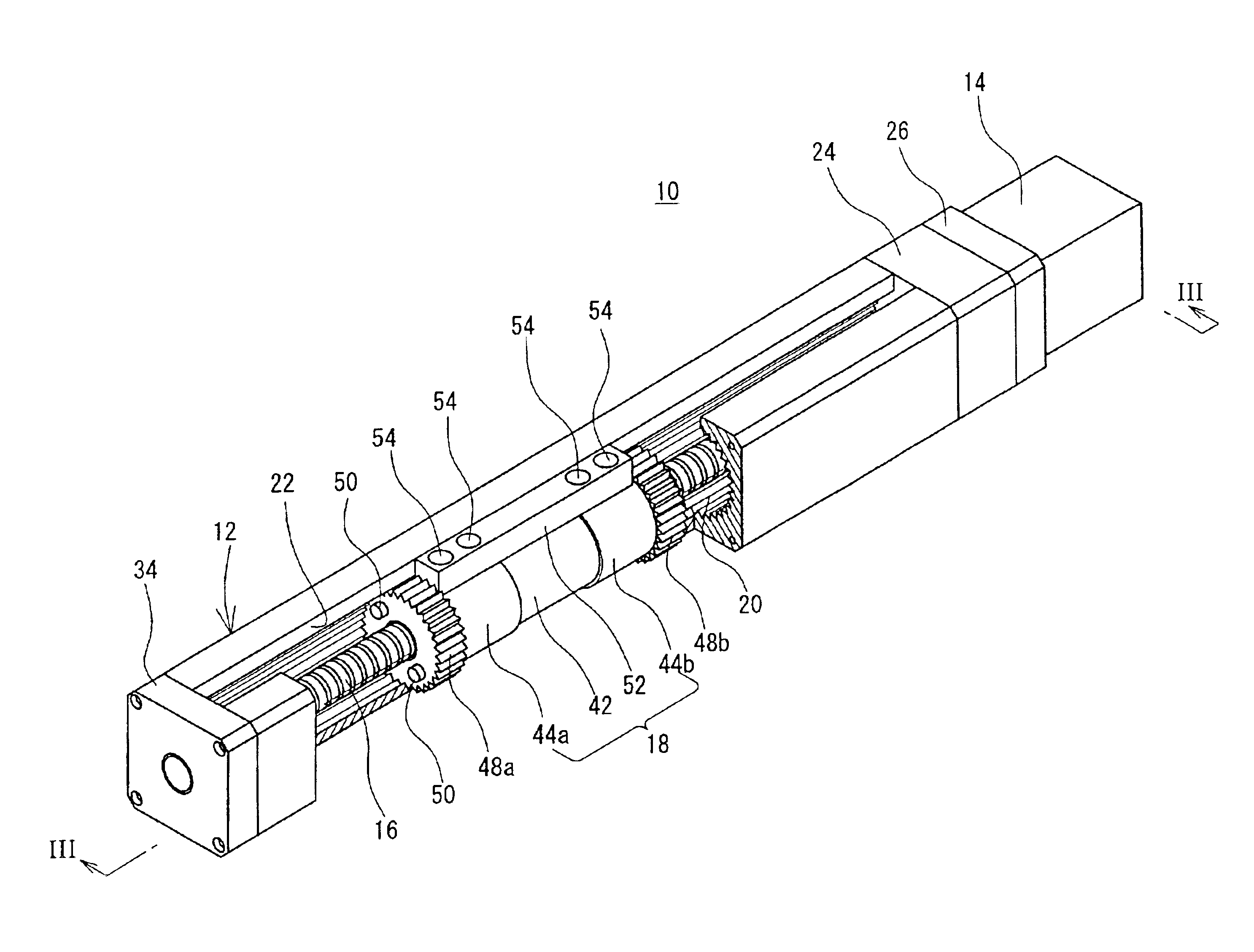
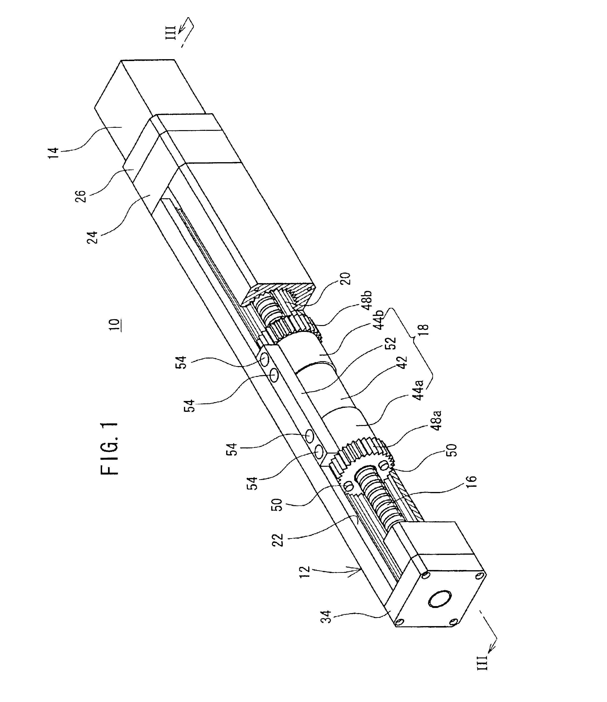
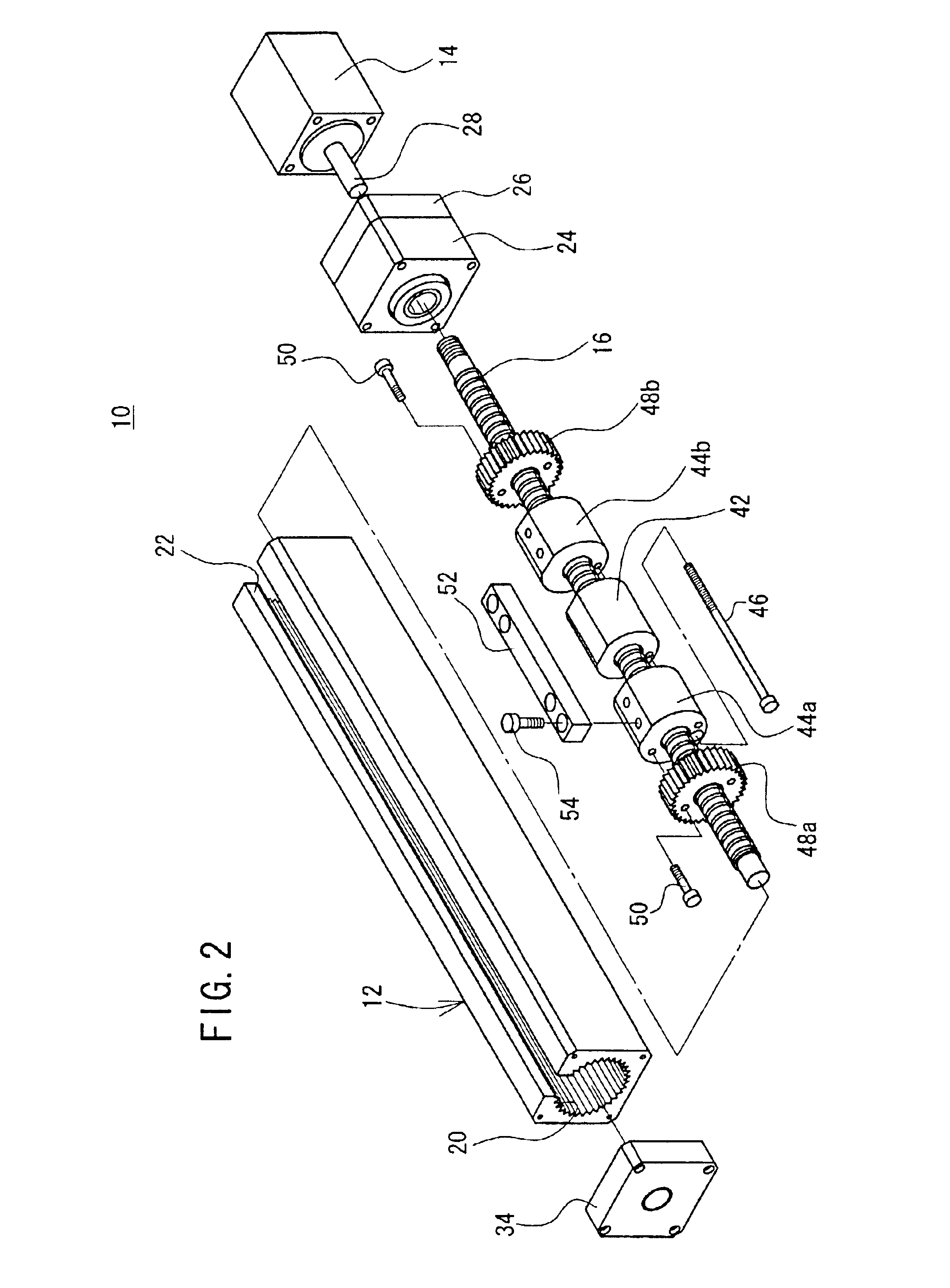
[0023]With reference to FIGS. 1 to 5, reference numeral 10 indicates an electric actuator according to an embodiment of the present invention. The electric actuator 10 basically comprises an elongated frame 12, a motor (rotary driving source) 14 which is provided at one end of the frame 12, a ball screw shaft 16 as a feed screw shaft which is rotatably supported in the frame 12, and a displacement mechanism 18 which is displaceable by the aid of the ball screw shaft 16.

[0024]The frame 12 is provided with a splined bore (spline guide mechanism) 20 which has involute splines (splines each having a spline tooth with an involute curve in cross section) extending in the longitudinal direction on the inner wall surface. A slit 22, which is communicated with the splined bore 20, is formed in the longitudinal direction through the upper surface of the frame 12. One end of a bearing member 24 is secured to one end of the frame 12 (see FIG. 2). A motor 14 is attached to the other end of the b...


PUM


Abstract

The rotary motion of a ball screw shaft is converted into the rectilinear motion by a ball spline nut provided integrally with displacement members by the aid of an attachment section. Involute splines are engraved on outer circumferential surfaces of spline pistons connected to the displacement members. The spline pistons are slidably meshed with a splined bore of the involute splines formed on an inner wall surface of a frame. The attachment section is displaceable in a longitudinal direction of the frame by the aid of the splined bore and the spline pistons.

Description

BACKGROUND OF THE INVENTION[0001]1. Field of the Invention[0002]The present invention relates to an electric actuator. In particular, the present invention relates to an electric actuator in which a displacement member makes rectilinear motion under a guiding action of a spline guide mechanism using an involute spline.[0003]2. Description of the Related Art[0004]Electric actuators, which use a feed screw mechanism, have been hitherto used as a means for transporting a workpiece or the like. The electric actuator comprises a feed screw shaft which is coaxially connected, via a coupling member, to a drive shaft of a motor in a frame. A feed nut, which is provided for a displacement member, is screw-engaged with the feed screw shaft. A linear guide mechanism including, for example, a guide rail and a guide block which slides along the guide rail is provided in the frame. The displacement member is linearly guided along the feed screw shaft. An attachment section, which protrudes to the...

Claims


Application Information

Patent Timeline
IPC IPC(8): F16H25/22F16H25/20F16H25/24H02K7/06
CPCF16H25/2204Y10T74/1868Y10T74/18656F16H2025/204F16H25/20
Inventor NAGAI, SHIGEKAZUMIYAHARA, MASAKIYAMASAKI, YOSHIYUKI
Owner SMC CORP
Why Eureka
Try Eureka