
Handheld spraying device with quick disconnect assembly

a spraying device and assembly technology, applied in the direction of spraying nozzles, movable spraying apparatuses, fluid pressure sealing joints, etc., can solve the problems of not meeting the widespread acceptance of devices, difficult to use,/or require the use of separate tools, and the mechanism is often relatively complicated, etc., to achieve convenient opening and closing, convenient insertion, and convenient retraction of the spray body

Inactive Publication Date: 2005-04-19
JING MEI IND HLDG LTD
View PDF21 Cites 55 Cited by
  • Summary
  • Abstract
  • Description
  • Claims
  • Application Information

AI Technical Summary

Benefits of technology

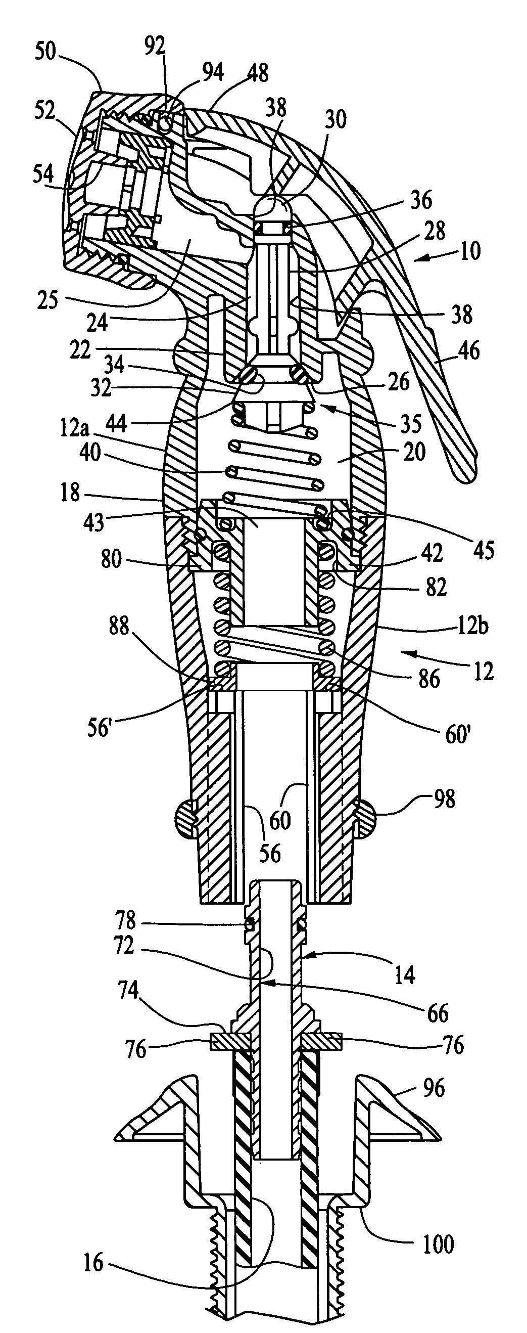
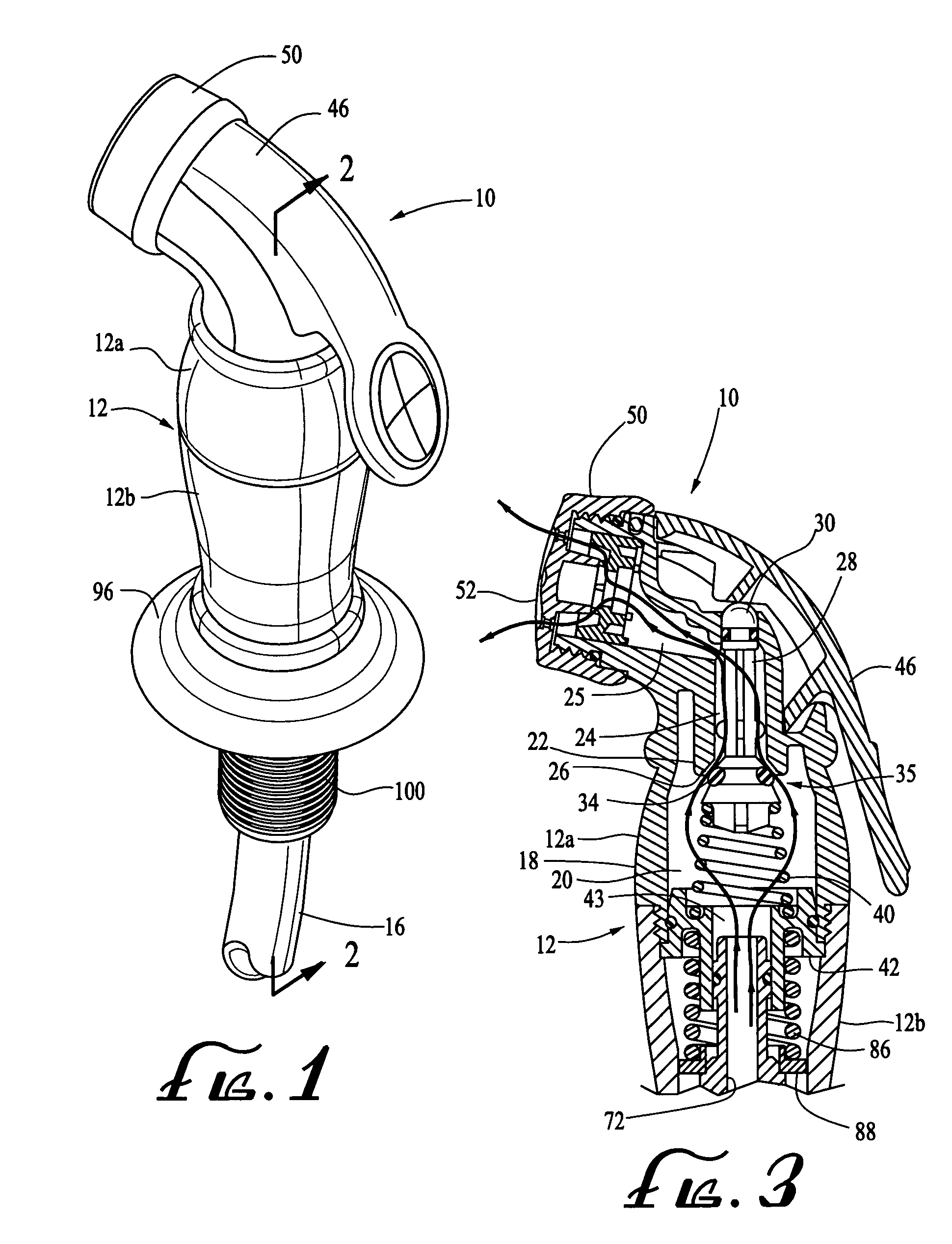
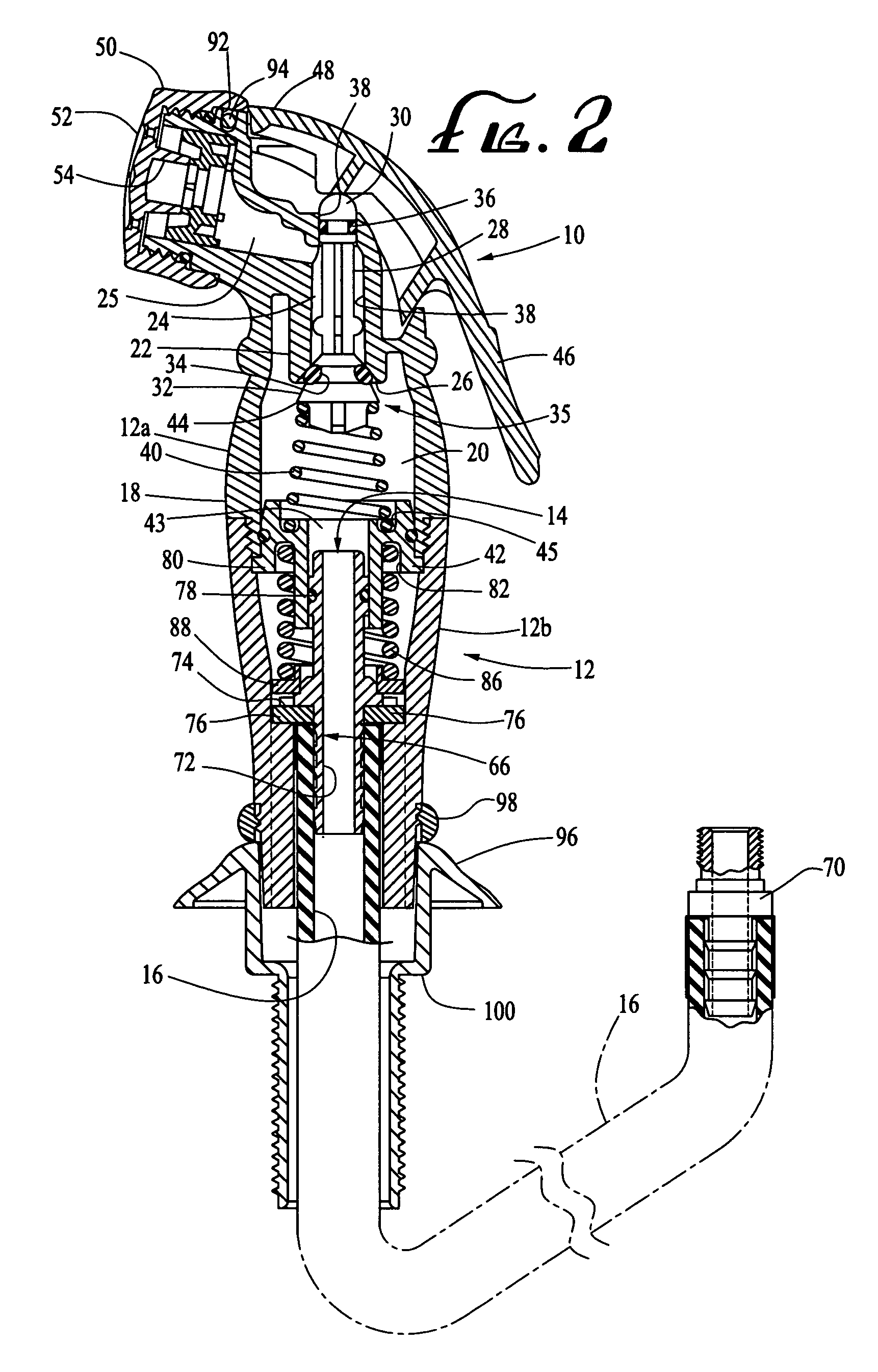
[0003]Briefly, the spraying device of the present invention comprises a handheld spray body that is removably mounted on a nozzle assembly fixed to a flexible water hose that is preferably retractably mounted adjacent a kitchen sink. The upper portion of the spray body defines the water spray outlet and houses a valve mechanism for selectively communicating pressurized water from the flexible hose with the spray outlet. A trigger mechanism is carried on the upper body portion for conveniently opening and closing the valve mechanism. To provide the quick disconnect of the spray body and the components housed therein, the nozzle assembly is provided with a pair of opposed radially projecting wing portions. The lower body portion of the device defines a radially oriented slot therein through which the nozzle and projecting wing portions can be readily inserted. Disposed adjacent and transversely of the radial slot are a pair of opposed seats for the wing portions of the nozzle assembly. A spring within the housing continually urges the nozzle assembly to a retracted position such that when the nozzle wing members are disposed within the seats formed in the lower body portion, the wing members are urged against their seats, securing the nozzle assembly within the lower body portion of the device with the flexible water hose in fluid communication with the spray body.
[0004]To disconnect the spray body from the water hose and affixed nozzle, it is only necessary to push the hose and nozzle a short distance into the lower portion of the body against the force of the spring therein such that the projecting wings on the nozzle will clear their respective seats. A 90° rotation of the hose relative to the spray body will then bring the wings into alignment with the slot in the lower body portion, enabling the hose and nozzle to be readily withdrawn from the spray body. To re-secure the nozzle to the same spray body or one having a different spray pattern or size, it is only necessary to realign the wing portions projecting from the nozzle with the interior slot in the lower portion of the spray body, insert the nozzle into the housing such that the wing portions pass through the slot and beyond the transversely disposed wing seats, rotate the flexible water hose and attached nozzle 90° with respect to the housing to align the wing portions with their respective seats and release the hose. The spring will press the nozzle outwardly, urging the projecting wings portion carried thereby into and against their aligned seats, thereby re-securing the hose and nozzle to the spray body.

Problems solved by technology

While a variety of quick disconnect mechanisms have heretofore been developed to permit quick and easy disassembly of a spray nozzle for cleaning or replacement, such mechanisms are often relatively complicated and thus are relatively expensive to manufacture and difficult to use and / or require the use of separate tools.
As a result, such devices have not met with widespread acceptance.

Method used


Image

  • Handheld spraying device with quick disconnect assembly
  • Handheld spraying device with quick disconnect assembly
  • Handheld spraying device with quick disconnect assembly

Examples


Embodiment Construction

[0016]Referring now in detail to the drawings, the handheld spraying device 10 of the present invention comprises a body 12 that is releasably secured by a quick disconnect assembly 14 to a conventional flexible water hose 16 of the type that is typically retractably mounted adjacent a kitchen sink. Spray body 12 has an upper body portion 12a defining an outer depending skirt 18 extending about an interior chamber 20 and threadably engaging a lower body portion 12b. The upper body portion 12a also defines an interior depending annular wall 22 at the upper end of chamber 20. Wall 22 extends about and defines a second chamber 24 and terminates at its lower end in an inclined surface defining a valve seat 26.

[0017]A valve piston 28 is reciprocally mounted in the second chamber 24 and defines an actuator button 30 at its upper end, and an inclined annular surface 32 proximate its lower upstream end that is adapted to mate with valve seat 26. An O-ring 34 is provided in an annular reces...


PUM


Abstract

A handheld spraying device having a quick disconnect assembly for releasably securing a spray body having a valve mechanism therein to a water line. The device includes a nozzle assembly affixed to a water line that includes a pair of opposed projecting wing portions that are spring biased into a pair of opposed seats formed in the spray body. An elongated opening transversely aligned with the seats is provided in the spray body for the passage of the nozzle assembly therethrough upon the wing portions thereof being aligned with the opening. Upon urging the nozzle assembly inwardly within the spray body against an interior spring so as to raise the wing portions off the seats and rotating the line and affixed nozzle assembly approximately 90° with respect to the spray body, the line and nozzle assembly can be withdrawn, disconnecting the spray body from the line.

Description

BACKGROUND OF THE INVENTION[0001]The present invention relates to a handheld spraying device adapted for at-home kitchen use and, more particularly, to such a device employing a quick disconnect feature that allows the user to replace the spraying mechanism with mechanisms of different shapes, sizes and spraying features without having to replace the connecting hose assembly.[0002]Handheld spraying devices are becoming increasingly popular for in-home kitchen use for a variety of applications ranging from dishwashing to the spraying of vegetables. For different applications, different nozzle sizes and shapes and spraying patterns are preferred. While a variety of quick disconnect mechanisms have heretofore been developed to permit quick and easy disassembly of a spray nozzle for cleaning or replacement, such mechanisms are often relatively complicated and thus are relatively expensive to manufacture and difficult to use and / or require the use of separate tools. As a result, such dev...

Claims


Application Information

Patent Timeline
Patent Type & Authority Patents(United States)
IPC IPC(8): B05B7/02B05B3/02B05B15/00B05B15/06B05B9/01B05B9/00B05B1/30B05B1/00B05B11/02F16L19/00F16L17/00
CPCB05B15/066B05B1/302B05B15/652
Inventor LAU, PING WA
Owner JING MEI IND HLDG LTD
Learn More