Apparatus and method for reinforcing concrete using rebar supports

a technology of rebar supports and rebar, which is applied in the direction of paving reinforcements, auxiliary members of forms/shuttering/falseworks, and ways. it can solve the problems of time and energy required to suspend the rebar in place using concrete forms, time-consuming to place and tie each section of the rebar in place, and not without certain limitations

a technology of rebar supports and rebar, which is applied in the direction of paving reinforcements, auxiliary members of forms/shuttering/falseworks, and ways. it can solve the problems of time and energy required to suspend the rebar in place using concrete forms, time-consuming to place and tie each section of the rebar in place, and not without certain limitations

US6883289B2Inactive Publication Date: 2005-04-26JUEDES BRIAN M +2

Image

  • Apparatus and method for reinforcing concrete using rebar supports
  • Apparatus and method for reinforcing concrete using rebar supports
  • Apparatus and method for reinforcing concrete using rebar supports

Examples


Embodiment Construction

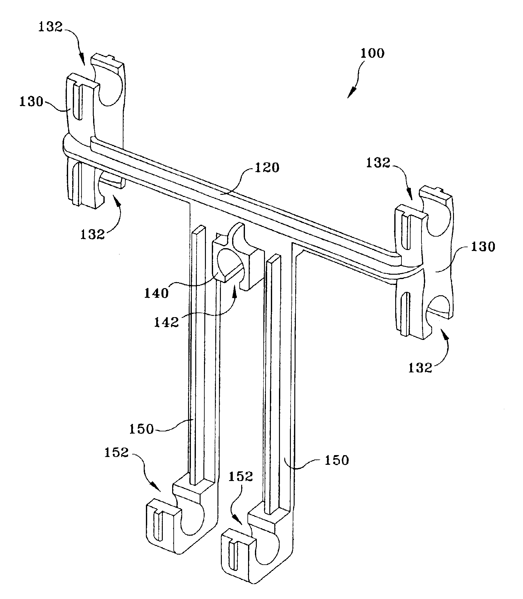
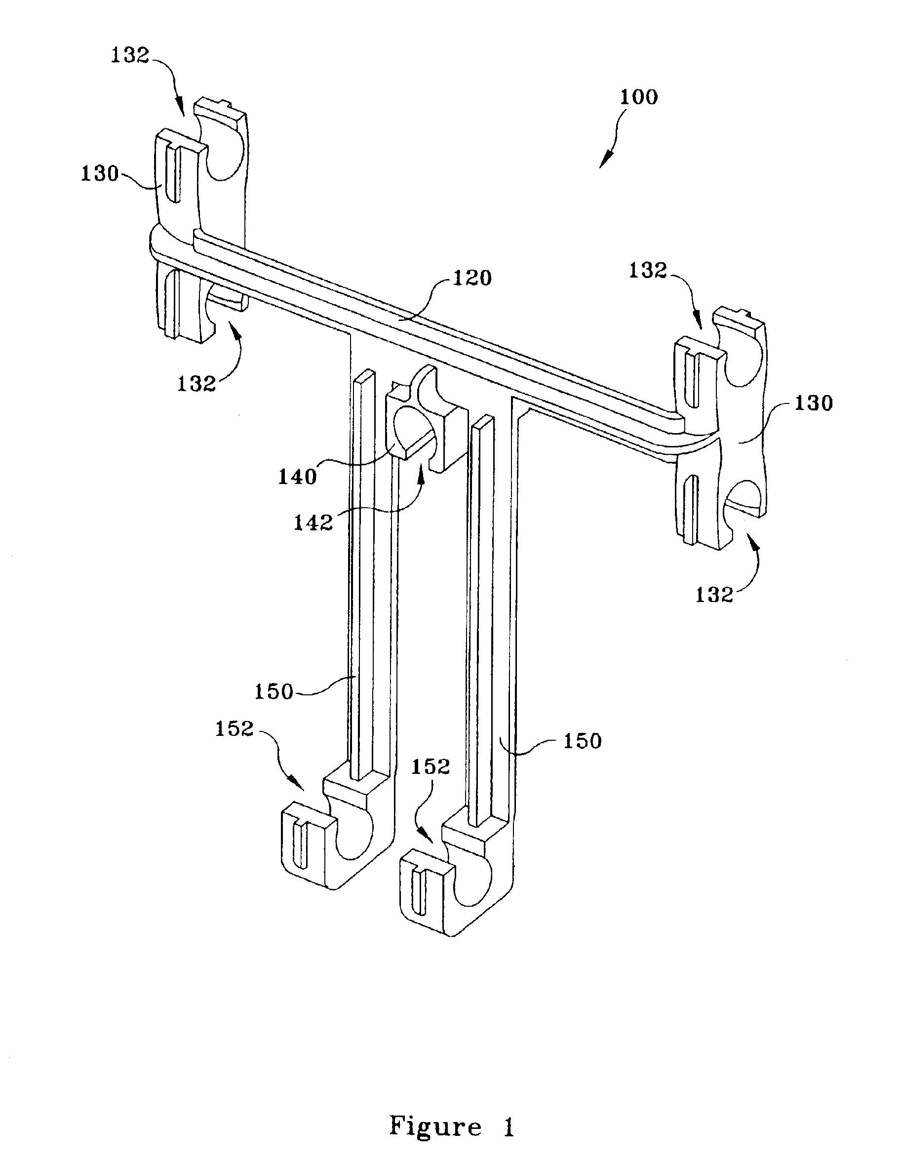
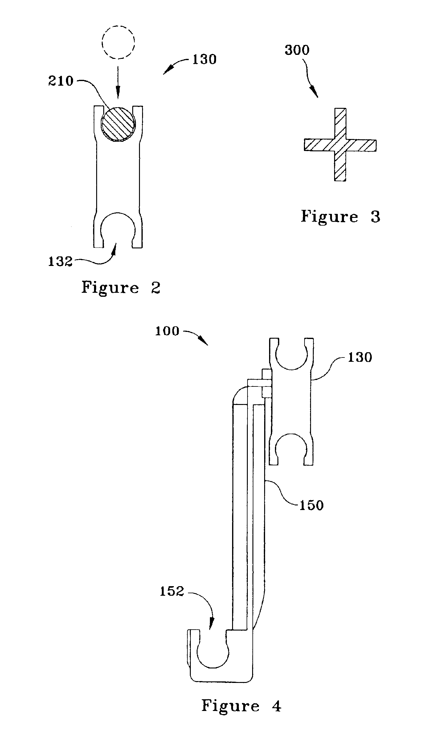
[0020]Referring now to FIG. 1, a rebar support 100 according to the most preferred embodiment of the present invention is shown. Rebar support 100 comprises: a horizontal portion 120; a pair of rebar support arms 130; a tendon support portion 140; and a pair of vertical support stabilizers 150. Rebar support arms 130 are configured to receive one or more lengths of rebar and securely hold the rebar in a desired position.

[0021]Each rebar support arm 130 is coupled to horizontal portion 120 and comprises at least one rebar-receiving portion 132 and each rebar-receiving portion 132 is sized and configured to receive a piece of rebar. The exact size of rebar-receiving portions 132 will be determined based on the specific application. Those skilled in the art will recognize that many different sizes are available for use and rebar-receiving portion 132 can be sized accordingly. While it is possible to create a rebar support 100 with a single support arm 130 and / or a single vertical suppo...


PUM


Abstract

The present invention provides an apparatus and method for suspending and positioning structural reinforcement elements such as rebar within a framework for a slab-on-grade foundation or other type of concrete structure. Each rebar support of the present invention comprises a plurality of rebar support arms that, in concert with the other components of the foundation or concrete structure, supports one or more pieces of rebar in a desired orientation.

Description

[0001]This application claims the benefit of U.S. Provisional application No. 60 / 428,482, filed on Nov. 22, 2002.BACKGROUND OF THE INVENTION[0002]1. Technical Field[0003]The present invention relates to suspending and positioning metal reinforcing bars (rebar) in the footings and foundations of buildings and other structures.[0004]2. Background Art[0005]Pre-stressed concrete is a type of reinforced concrete that has been subjected to an external compressive force prior to the application of loads. Typical applications for pre-stressed concrete include slab-on-grade construction and the like. The compressive force in the concrete slab is typically provided by placing steel tendons within the concrete that are initially tensioned with hydraulic jacks and held in tension by end anchors secured to the foundation forms.[0006]Pre-stressed concrete may be broadly categorized as either pre-tension or post-tension. Pre-tension refers to the method of first stressing tendons and then casting ...

Claims


Application Information

Patent Timeline
26 Apr 2005
Publication
US6883289B2
IPC
E04C5/16
CPC
E04C5/163; E04C5/168; E04C5/167
Inventors
JUEDES, BRIAN M.; TOONE, BRYAN D.