Bead dispensing system

a technology of dispensing system and beads, which is applied in the direction of coin-freed apparatus details, burettes/pipettes, chemical library materials, etc., can solve the problems of clogging of nozzles, too slow for cost-effective operations, and inability to optimize each separate fluid

Inactive Publication Date: 2005-05-03
APPL BIOSYSTEMS INC
View PDF61 Cites 86 Cited by
  • Summary
  • Abstract
  • Description
  • Claims
  • Application Information

AI Technical Summary

Benefits of technology

[0034]In one embodiment, a pair of indexing pins extends below the compliant surface. Further in this embodiment, the micro-card is provided with a pair of spaced-apart indexing bores or slots, with each being alignable with one of the indexing pins. Registration of the indexing pins with the bores or slots serves to orient the shearing blade over the micro-card for effecting a cut in the web. In a related embodiment, the shearing blade has a cutting edge defining

Problems solved by technology

Unfortunately, for the purpose of depositing numerous substances into the wells of a micro-card or plate, each of these devices is associated with certain disadvantages.
However, when depositing many different fluids through the same nozzle, optimization for each separate fluid is often impractical.
As a result, the nozzles can become clogged.
With regard to pens and quills, these devices can collide with the well walls, and are generally too slow for cost-effective operations.
The task of delivering micro-volumes of fluidic substances can be especially challenging when the substance deposited at each location is unique to one or only a few positions in the array.
Further complications can arise when mu

Method used


Image

  • Bead dispensing system
  • Bead dispensing system
  • Bead dispensing system

Examples


Embodiment Construction

[0083]The following discussion of the preferred embodiments of the present invention is merely exemplary in nature. Accordingly, this discussion is in no way intended to limit the scope of the invention.

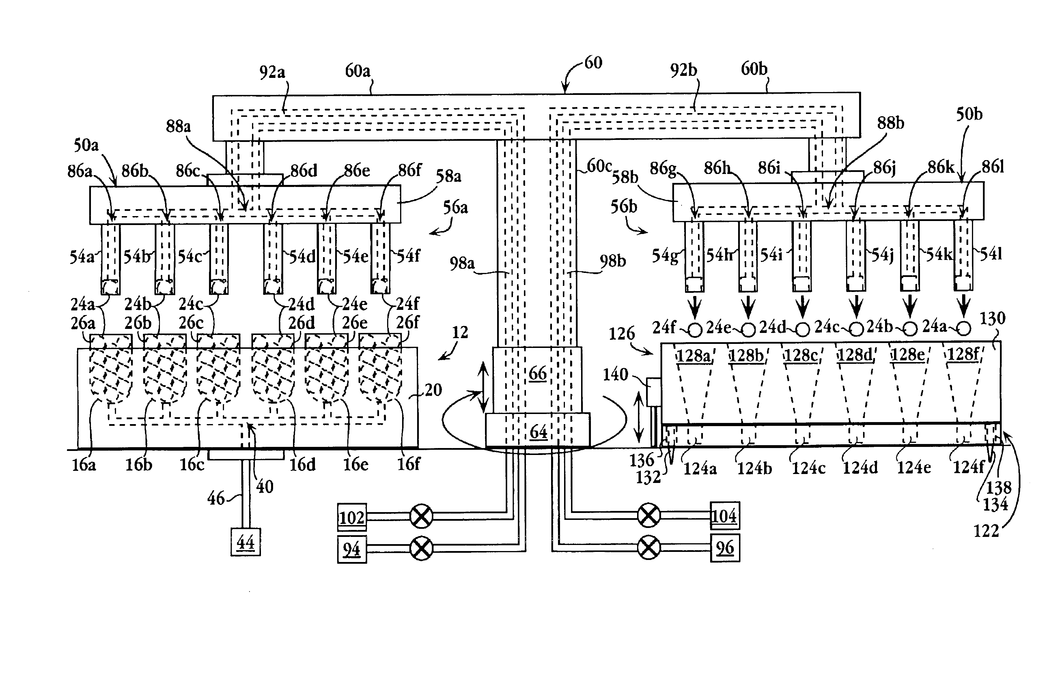
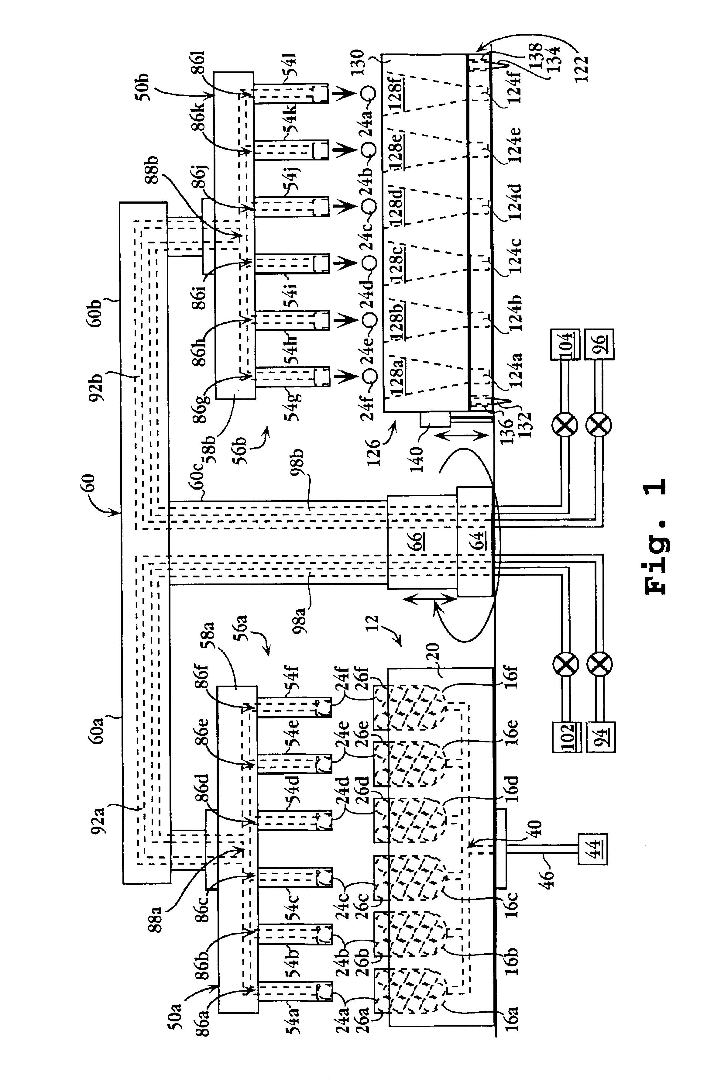
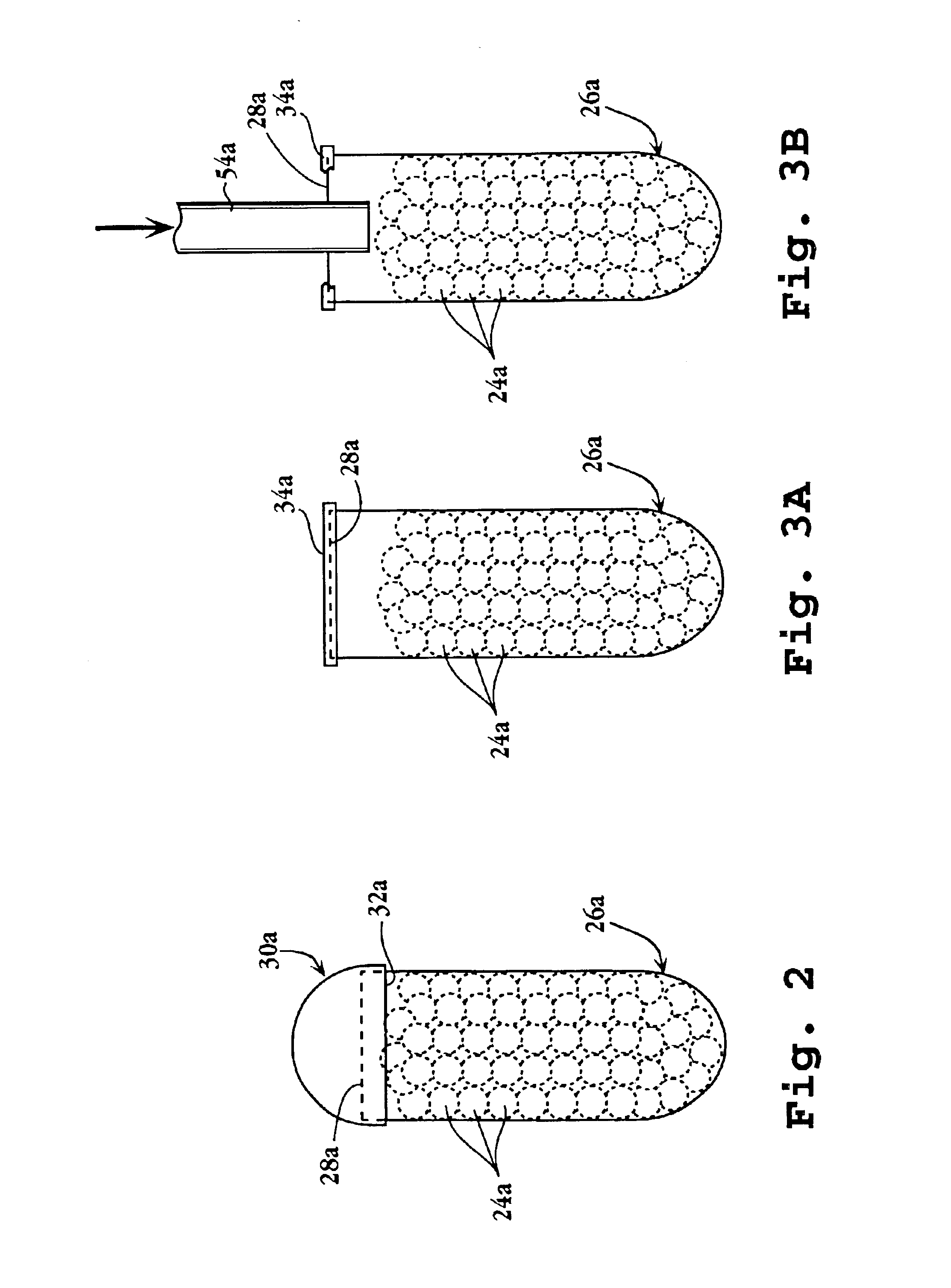
[0084]One aspect of the present invention provides a system for picking up a plurality of small, reagent-carrying beads from a supply or source area and transferring them onto a substrate, e.g., wells in a micro-card or plate. Generally, the system includes a plurality of projections depending from a movable support structure at fixed, spaced-apart locations. A cavity is provided at a lower end region of each of the projections, defined by a (i) lower opening, (ii) an upper ceiling, and (iii) a sidewall extending between the lower opening and upper ceiling. An attraction source is operable at each of the projection end regions in a manner effective to draw individual beads from the supply into respective cavities and to releasably retain them therein. While retained in the cavities, ...


PUM


Abstract

A bead dispensing system is provided for delivering small amounts of substances onto substrates. The system can include, for example, a movable support structure having an array of spaced-apart projections depending from its lower side. An attraction source, such as a vacuum, magnetic, and/or electrostatic force, is operable at each projection end region to attract and retain one bead. The projection array can be aligned with an array of bead-receiving regions of a substrate, e.g., an array of spaced-apart wells of a micro-plate or card. In one embodiment, a plurality of reagent-carrying beads are picked up, retained at respective projection end regions, and moved to a location over a multi-well plate. The beads are then released in a fashion permitting each bead to land in a respective well. The system of the invention is particularly useful for fabricating arrays of reagents.

Description

[0001]This application is a Continuation-in-Part of U.S. application Ser. No. 09 / 250,697 filed Feb. 16, 1999, now abandoned, which is incorporated herein by reference.FIELD OF THE INVENTION[0002]The present invention relates to the manipulation of small beads capable of carrying substances such as reagents or samples, and the like. More particularly, the invention provides a method and apparatus for fabricating an array of such beads on a micro-card or plate.BACKGROUND OF THE INVENTION[0003]Multi-well arrays have long been popular for separately performing numerous chemical and / or biological reactions at substantially the same time. Perhaps the most popular multi-well format in recent years has been the 96-well microplate. Typically, several microliters of reagents are placed in each of the 96 reaction wells, per assay. In an effort to decrease reagent costs, as well as to increase throughput, many laboratory directors are now moving toward the use of even higher-density plates havi...

Claims


Application Information

Patent Timeline
IPC IPC(8): B01L11/00B01L3/02B01J19/00G01N35/10B01L99/00C40B40/06C40B60/14G01N33/53C40B70/00G01N35/00G01N37/00
CPCB01J19/0046B01L3/021B01L3/0289B01L3/563B82Y30/00G01N35/10G01N35/1065Y10T436/255B01J2219/00308B01J2219/00315B01J2219/00317B01J2219/00369B01J2219/00468B01J2219/005B01J2219/00545B01J2219/00549B01J2219/00585B01J2219/00596B01J2219/00648B01J2219/0065B01J2219/00659B01J2219/00677B01J2219/00689B01J2219/00691B01J2219/00693B01J2219/00702B01J2219/00722B01L2200/021B01L2200/0647B01L2200/0657B01L2200/143B01L2300/0654B01L2300/0864B01L2400/0415B01L2400/043B01L2400/0487B01L2400/049C40B40/06C40B60/14C40B70/00G01N2035/00574Y10T436/11Y10T436/2575B01J2219/00283
Inventor VANN, CHARLES S.LEHTO, DENNIS
Owner APPL BIOSYSTEMS INC
Why Eureka
Try Eureka