Power tool with light emitting diode

a technology of light-emitting diodes and power tools, which is applied in the direction of multi-purpose tools, manufacturing tools, and portable power-driven tools. it can solve the problems of poor lighting, cumbersome use of tools, and reduced visibility

Inactive Publication Date: 2005-05-10
CREDO TECH CORP
View PDF95 Cites 81 Cited by
  • Summary
  • Abstract
  • Description
  • Claims
  • Application Information

AI Technical Summary

Problems solved by technology

Such visibility can be reduced by a build-up of cutting debris (e.g., sawdust) and poor lighting at the point of the cut.
However, the use of such a vacuum system often makes use of the tool more cumbersome.
Proper lighting at the point of a cut can be a problem, both in generally poorly lighted construction environments and, more generally, in any environment where the operator of the tool and the tool itself cast a shadow over the workpiece.

Method used


Image

  • Power tool with light emitting diode
  • Power tool with light emitting diode
  • Power tool with light emitting diode

Examples


Embodiment Construction

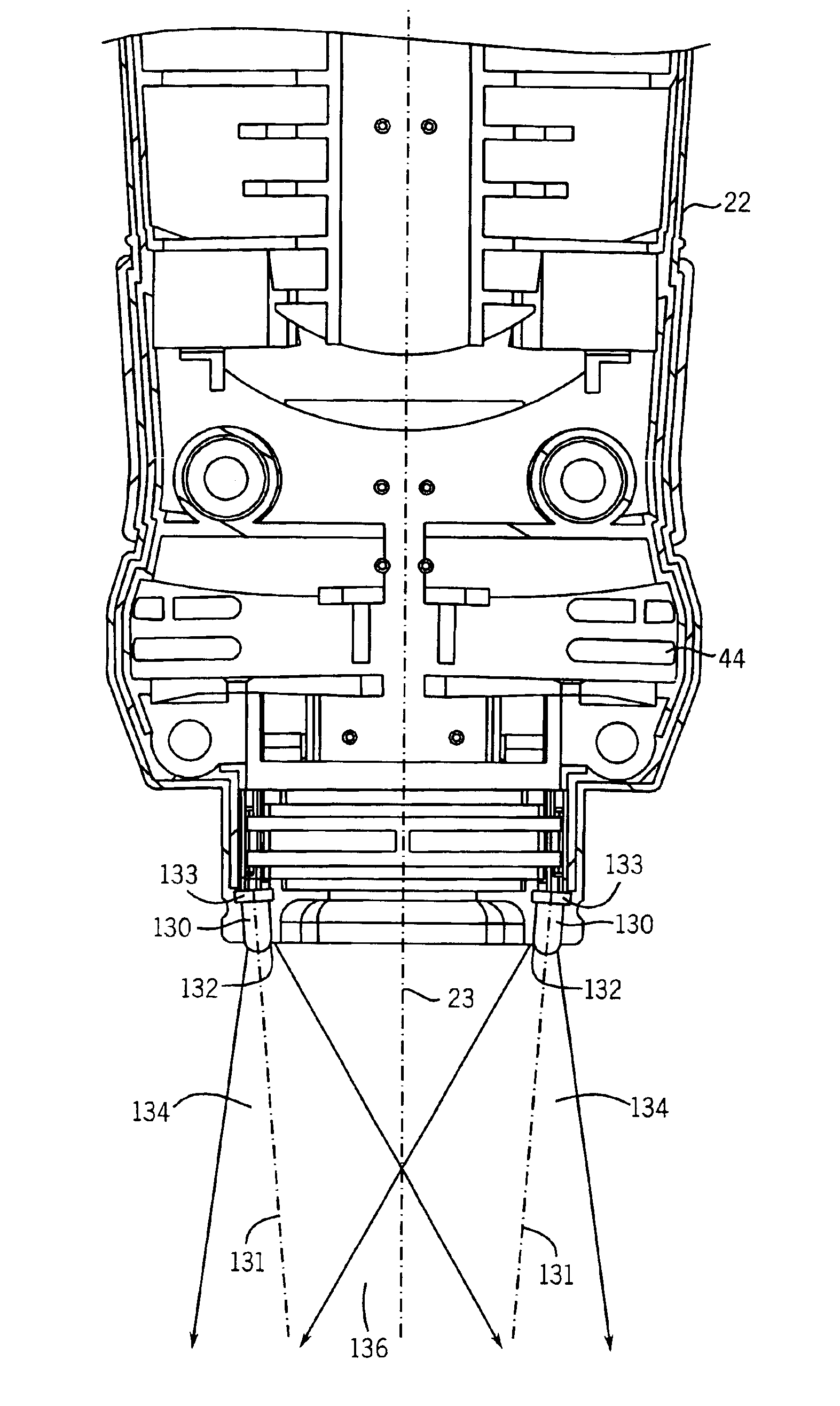
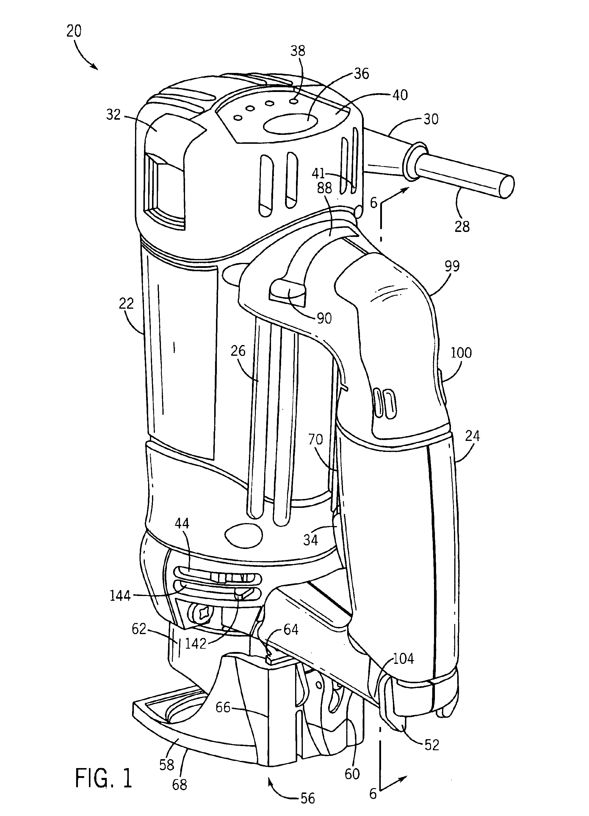
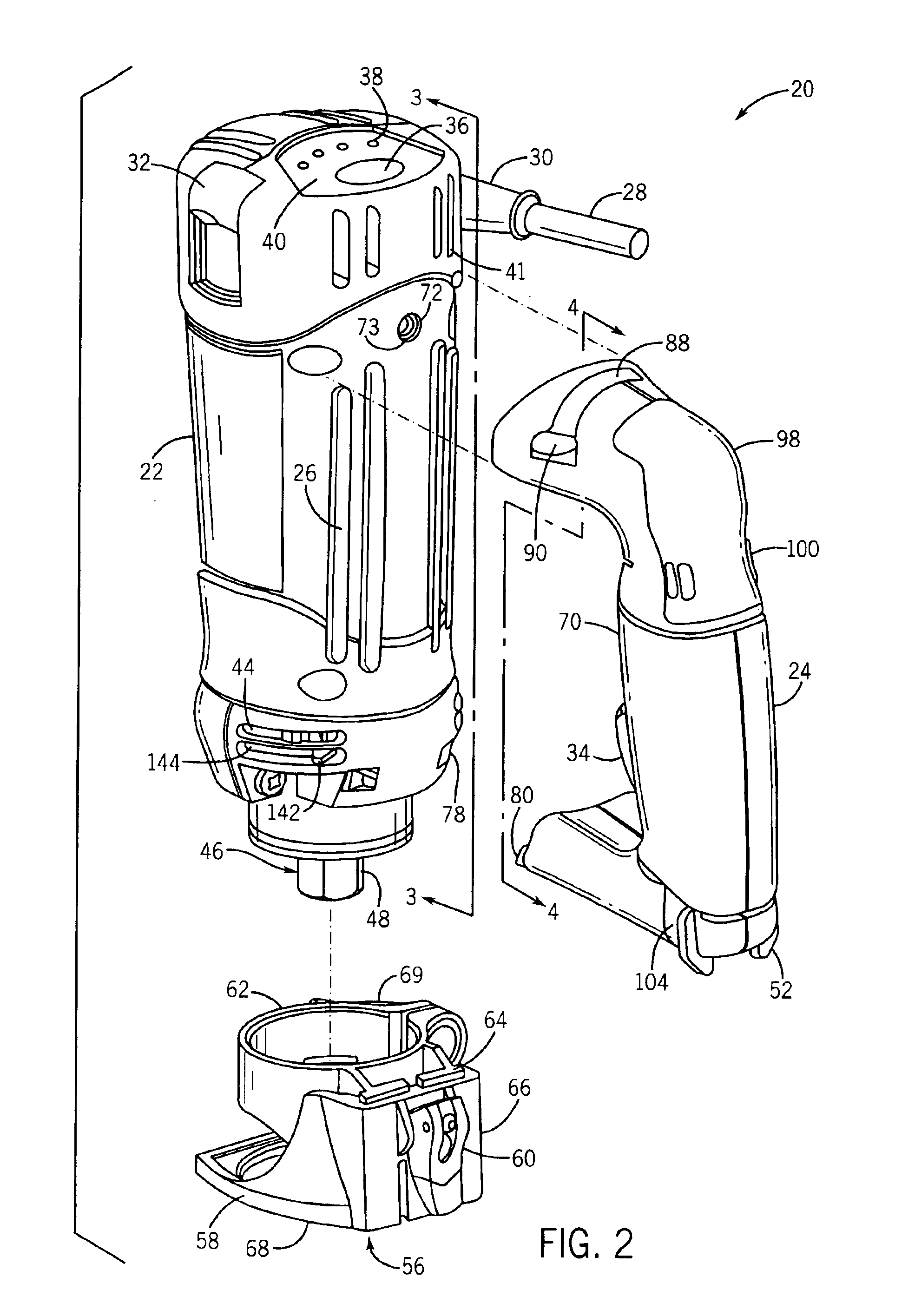
[0022]A hand-held rotary power or cutting tool 20 including features for improving the ability of an operator to operate and control the tool is shown generally in FIGS. 1 and 2. It should be understood that, although the present invention will be described in detail herein with reference to the exemplary embodiment of a rotary cutting tool 20, the present invention may be applied to, and find utility in, other types of hand-held power tools as well.

[0023]The rotary cutting tool 20 includes a motor housing 22 to which a detachable handle 24 is attached. The motor housing 22 is preferably made of an electrically insulating material, such as hard plastic. The motor housing 22 is generally cylindrical in shape, and may include raised gripping surfaces 26 formed thereon that allow a firm grip on the rotary cutting tool 20 to be maintained when the rotary cutting tool 20 is grasped around the motor housing 22. The motor housing 22 may be formed as two or more molded pieces which are join...


PUM

PropertyMeasurementUnit
depth of cutaaaaaaaaaa
rotationaaaaaaaaaa
angleaaaaaaaaaa

Abstract

A rotary cutting tool includes a housing and a motor provided within the housing for rotating a cutting accessory coupled to the rotary cutting tool. The rotary cutting tool also includes a plurality of light emitting diodes for illuminating a point of cut of the rotary cutting tool. Each of the plurality of light emitting diodes have a central longitudinal axis, and at least one of the light emitting diodes is couple to the housing such that the central longitudinal axis of the light emitting diode is not parallel to a rotation axis of the cutting accessory.

Description

CROSS-REFERENCE TO RELATED PATENT APPLICATIONS[0001]This application is a continuation of U.S. patent application Ser. No. 10 / 373,144 filed Feb. 24, 2003 (now abandoned), which is a continuation-in-part of U.S. patent application Ser. No. 10 / 189,899 filed Jul. 3, 2002 (now abandoned), which is a division of U.S. patent application Ser. No. 09 / 506,244 filed Feb. 17, 2000 (now U.S. Pat. No. 6,443,675). The entire disclosures of U.S. patent application Ser. No. 10 / 373,144 (now abandoned), U.S. patent application Ser. No. 10 / 189,899 (now abandoned), and U.S. patent application Ser. No. 09 / 506,244 (now U.S. Pat. No. 6,443,675) are expressly incorporated by reference herein.BACKGROUND OF THE INVENTION[0002]The invention relates generally to hand-held power tools. More specifically, the invention relates to hand-held power tools having at least one light emitting diode.[0003]Hand-held power tools, such as hand-held power cutting tools, generally include a housing and an electric motor cont...

Claims


Application Information

Patent Timeline
Patent Type & Authority Patents(United States)
IPC IPC(8): B25F5/00B25F5/02B27C5/00B27C5/10
CPCB25F5/02B25F5/026B27C5/10B25F5/021Y10T16/469Y10S29/082Y10S16/12Y10S16/24Y10S29/083Y10T409/304088Y10T409/306608Y10T408/21Y10T408/65Y10T403/595Y10T409/303976Y10T16/444Y10T409/308624B25F5/008Y10T83/68Y10T83/828Y10T83/2066Y10T83/242
Inventor KOPRAS, ROBERTKOPRAS, JASON R.ADLER, SCOTTSEALS, DOUGLASRINDY, RYANGUNSEOR, LARRYBULLIS, DANIEL
Owner CREDO TECH CORP
Why Eureka
Try Eureka