

Damping element
a damping element and a technology of a hollow-shaped body, applied in the direction of electrical transducers, instruments, electrical equipment, etc., can solve the problems of tearing the support off, the musician can trip over the microphone or its support, and the danger is increased
- Summary
- Abstract
- Description
- Claims
- Application Information
AI Technical Summary
Benefits of technology
Problems solved by technology
Method used
Image

Examples
Embodiment Construction
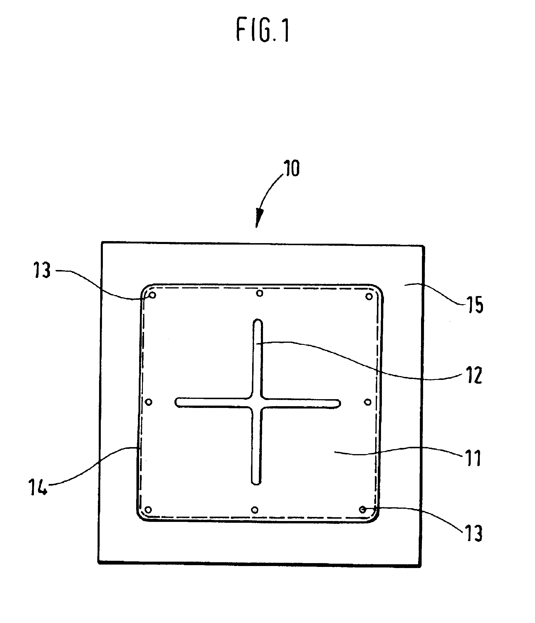
[0029]FIG. 1 shows a plan view of an upper side 15 of a damping element 10 that is formed as a pillow. On the upper side 15, there is provided an outer layer 11, which overlies a reinforcing plate 17 (not shown in FIG. 1). The outer layer 11 is formed of a rubber-like material and is secured to the upper surface 15 with a stitched seam 14. In addition, the outer layer 11 is secured to the reinforcing plate 17 with screws 13. In the outer layer 11, there is provided an opening 12 formed of two mutually crossing slots. The two slots from a guide slot for a holder 18 (not shown in FIG. 1).
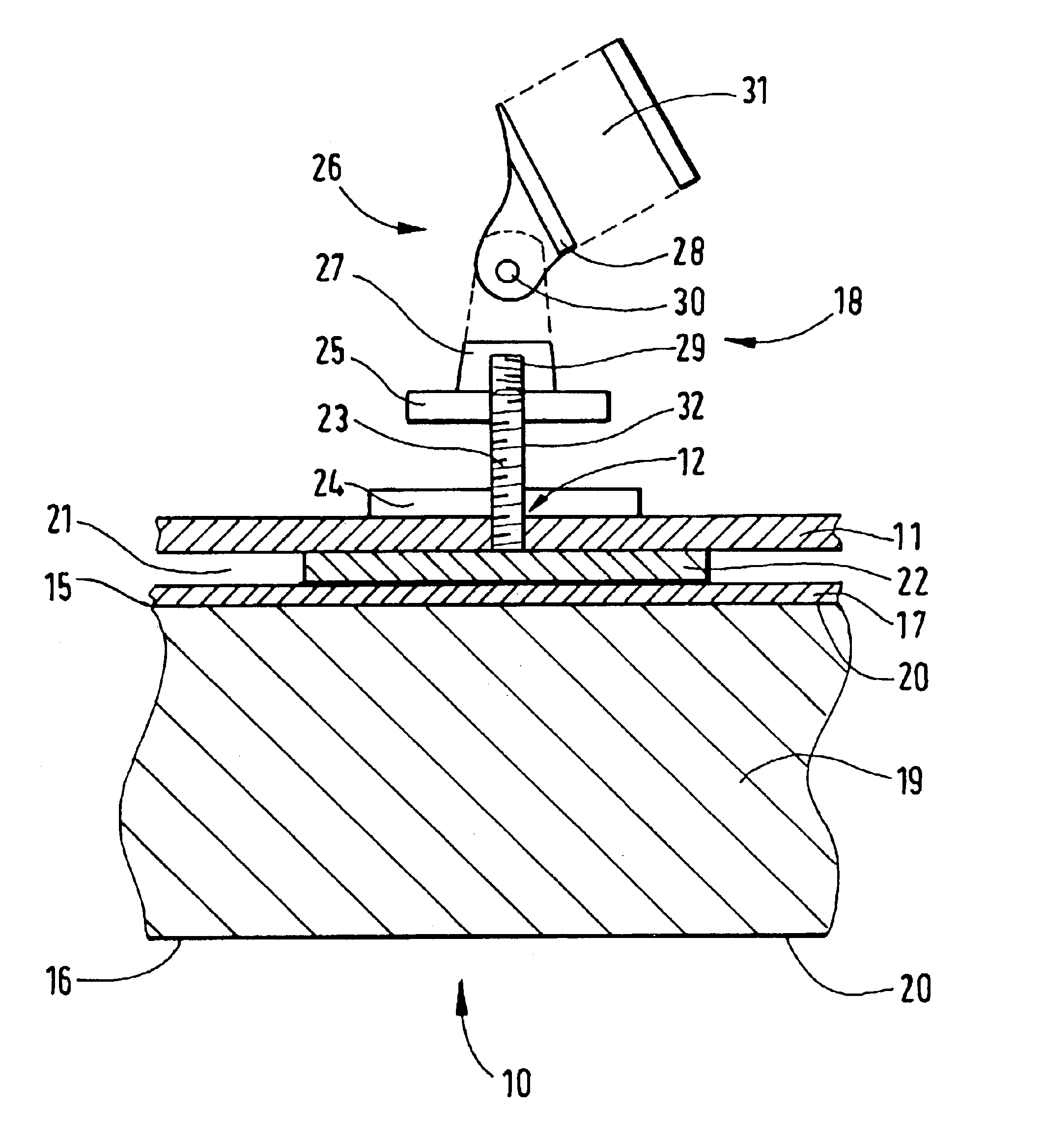
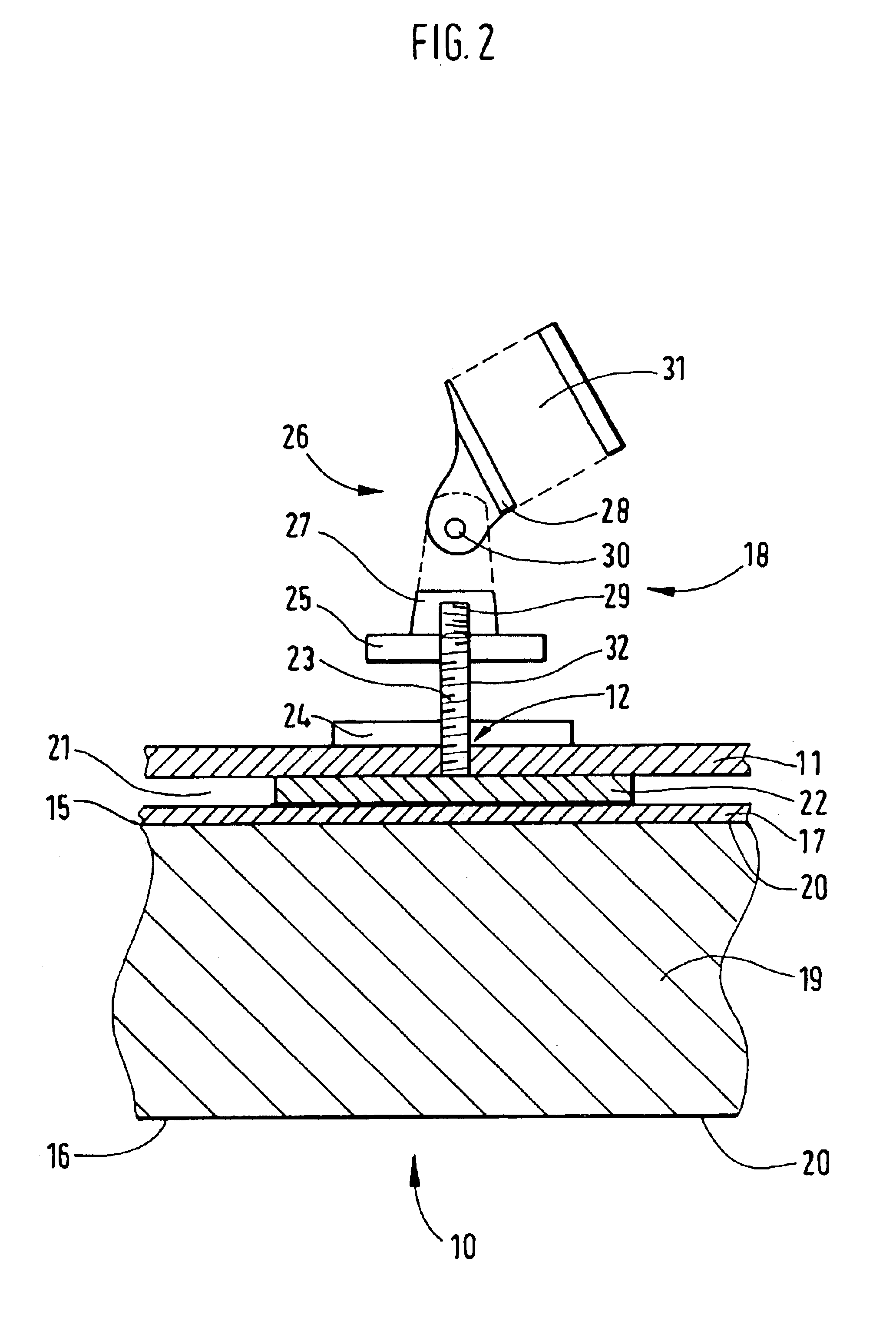
[0030]The holder 18, which is used for holding a microphone, is shown in detail in FIG. 2 a lower part of which shows a cross-section of the damping element 10. The interior of the damping element 10 is filled with a filling 19 consisting of sound absorbing material. The filling 19 is covered by cloth material 20, upper and lower sides of which are shown with reference numerals 15 and 16. As it has al...
PUM
 Abstract
Description
Claims
Application Information