Load reliever for plow moldboard

Inactive Publication Date: 2005-05-17
GLEDHILL ROAD MACHINERY
View PDF8 Cites 37 Cited by
  • Summary
  • Abstract
  • Description
  • Claims
  • Application Information

AI Technical Summary

Problems solved by technology

The plow is then operated with the moldboard in this state, which cases rapid wear on the trip board.
Some plow operators take the time to raise the lift arms to a sufficient degree that the lower edge of the moldboard rides at or very ne

Method used


Image

  • Load reliever for plow moldboard
  • Load reliever for plow moldboard
  • Load reliever for plow moldboard

Examples


Embodiment Construction

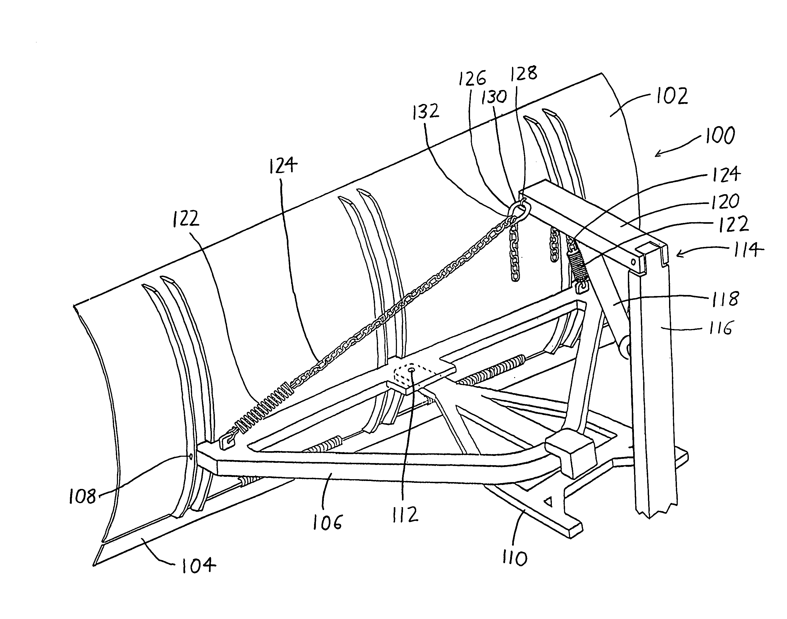
[0008]The invention involves a plow moldboard load relieving apparatus for effectively reducing the weight of a plow moldboard and associated components atop a trip board (or atop the lower edge of a moldboard, where a trip board is not present). The claims set forth at the end of this document define the various versions of the invention in which exclusive rights are secured. To provide the reader with a better understanding of some of the advantageous features of the invention, some preferred features will now be described in greater detail.

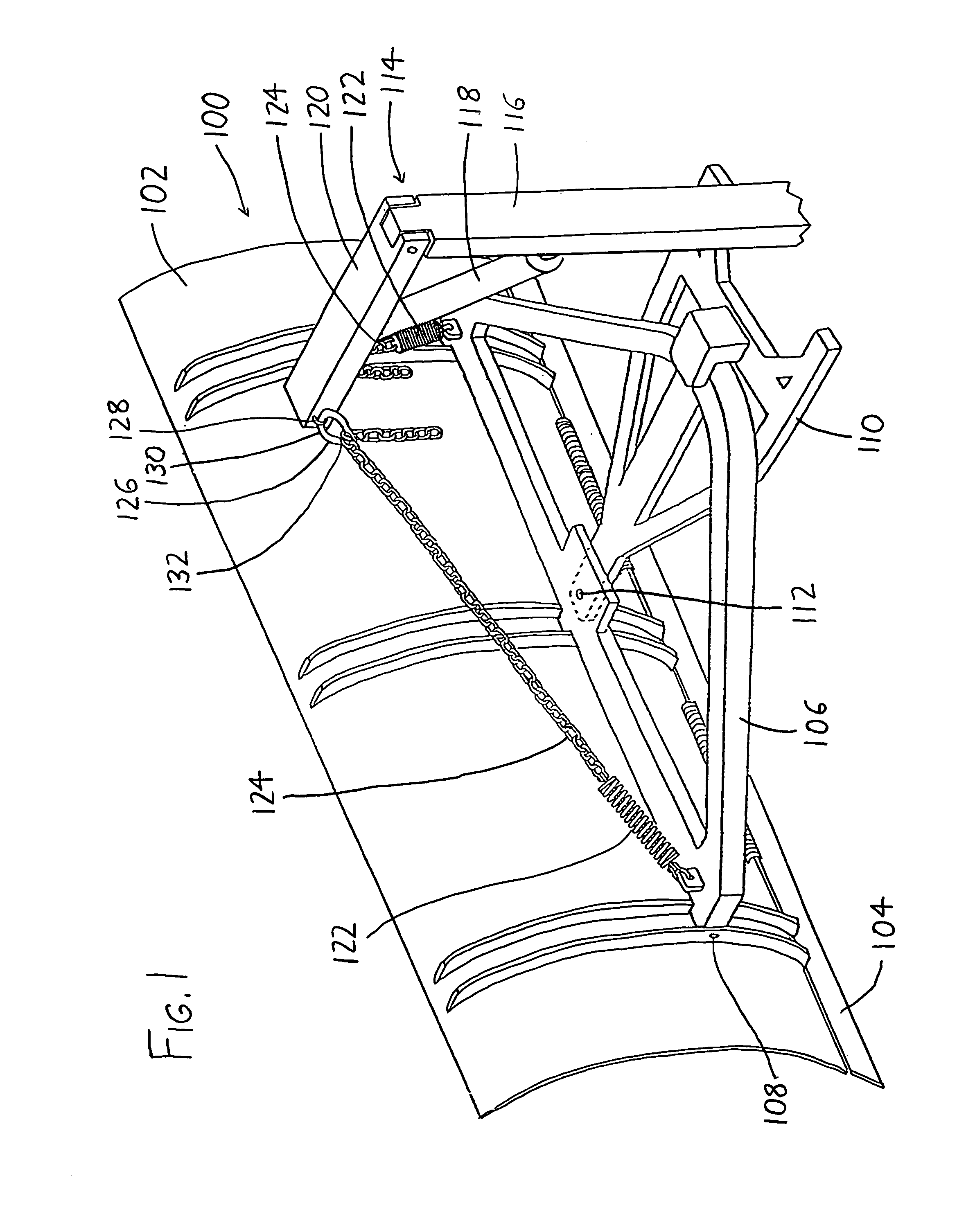
[0009]An exemplary version of the plow moldboard load relieving apparatus is shown in FIG. 1. A plow moldboard assembly 100 includes a moldboard 102, a lower tripboard 104 pivotally affixed to the lower length of the moldboard 102, and a reversing table 106 to which the moldboard 102 is pivotally mounted at pivots 108 to allow adjustment of the vertical angle of the moldboard 102 with respect to the surface being plowed. The moldboard assembly ...


PUM


Abstract

The invention alleviates wear on a plow moldboard by achieving a reduction in the effective weight of the moldboard on the roadway. One or more elastic links are interposed between the moldboard and the lifting arm which elevates and lowers the moldboard. The elastic links may be tensioned to such a degree that they serve as a counterweight for the moldboard, transmitting all or most of its weight to the lift arm and the plowing vehicle. The effective weight of the moldboard is thus reduced to such a degree that the lower edge of the moldboard bears against the roadway with little or no force, and it skids or slides along the roadway rather than grinding against it.

Description

CROSS-REFERENCE TO RELATED APPLICATIONS[0001]This application claims priority under 35 USC §119(e) to U.S. Provisional Patent Application 60 / 355,414 filed 7 Feb. 2002, the entirety of which is incorporated by reference herein.FIELD OF THE INVENTION[0002]This document concerns an invention relating generally to methods and apparata for enhancing the performance and lifespan of snowplow moldboards (i.e., snowplow “plowing blades”) and components thereof, and more specifically to methods and apparata for supporting snowplow moldboards and associated snowplow components upon or above the plowing surface during plowing operations.BACKGROUND OF THE INVENTION[0003]Snowplows generally have plow blades which include a moldboard and a trip board. A trip board is a plowing blade pivotally attached beneath the lower edge of a moldboard, and a torsion spring or other biasing device is situated between the moldboard and the trip board to maintain the trip board in a generally coplanar relationshi...

Claims


Application Information

Patent Timeline
IPC IPC(8): E01H5/06E01H5/04
CPCE01H5/06
Inventor GLEDHILL, GARLANDSPRINGER, JAMES
Owner GLEDHILL ROAD MACHINERY
Why Eureka
Try Eureka