Coaxial resonator, filter, duplexer, and communication device

a dielectric filter and coaxial resonator technology, applied in the direction of resonators, electrical devices, waveguides, etc., can solve the problems of loss caused, difficult to improve the characteristics of inner conductor films, and dielectric loss in dielectric portions, and achieve high power efficiency communication

Inactive Publication Date: 2005-05-17
MURATA MFG CO LTD
View PDF23 Cites 5 Cited by
  • Summary
  • Abstract
  • Description
  • Claims
  • Application Information

AI Technical Summary

Benefits of technology

[0013]Accordingly, the present invention provides a coaxial resonator, a filter, and a duplexer, which are compact and which have reduced loss, and a communication device using the same.
[0014]The present invention also provides a coaxial resonator, a filter, and a duplexer in which it is easy to form an inner conductor having characteristics beneficial to reduce losses, and a communication device using the same.
[0015]In one aspect of the present invention, a coaxial resonator includes an inner conductor formed on an outer surface of a columnar element, a dielectric element having a hole formed therein for receiving the columnar element, and an outer conductor formed on an outer surface of the dielectric element. Since the inner conductor is formed on the outer surface of the columnar element, an inner conductor comprising an improved conductor film which is capable of reducing the conductor loss can be easily formed, and disposed so as to be isolated from the dielectric element.

Problems solved by technology

Since the coaxial resonator is structured with a conductor film deposited on an inner surface of a hole formed in the dielectric block, it is difficult to improve the characteristics of the inner conductor film, as compared with those of the outer conductor formed on an outer surface of the dielectric block.
The resonator losses typically include conductor loss caused by the conductor films, dielectric loss in dielectric portions, and radiation loss due to radiation to the outside.
Hence, making the conductor film thicker than the skin depth provides substantially no advantage with respect to reducing the conductor loss.
However, it is difficult to form either a thin-film, multi-layer electrode or to form a multiplexed inner conductor on an inner surface of a hole having a small inner diameter.

Method used


Image

  • Coaxial resonator, filter, duplexer, and communication device
  • Coaxial resonator, filter, duplexer, and communication device
  • Coaxial resonator, filter, duplexer, and communication device

Examples


first embodiment

[0035]A coaxial resonator according to the present invention is described with reference to FIGS. 1A, 1B, and 2.

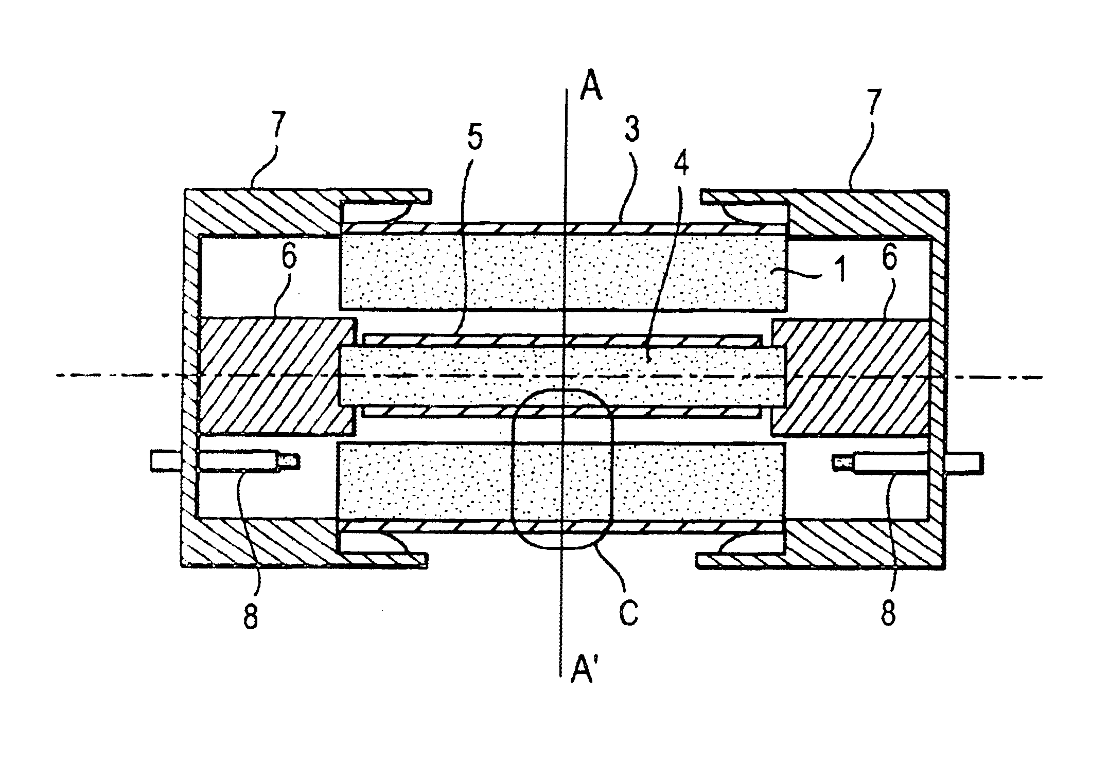
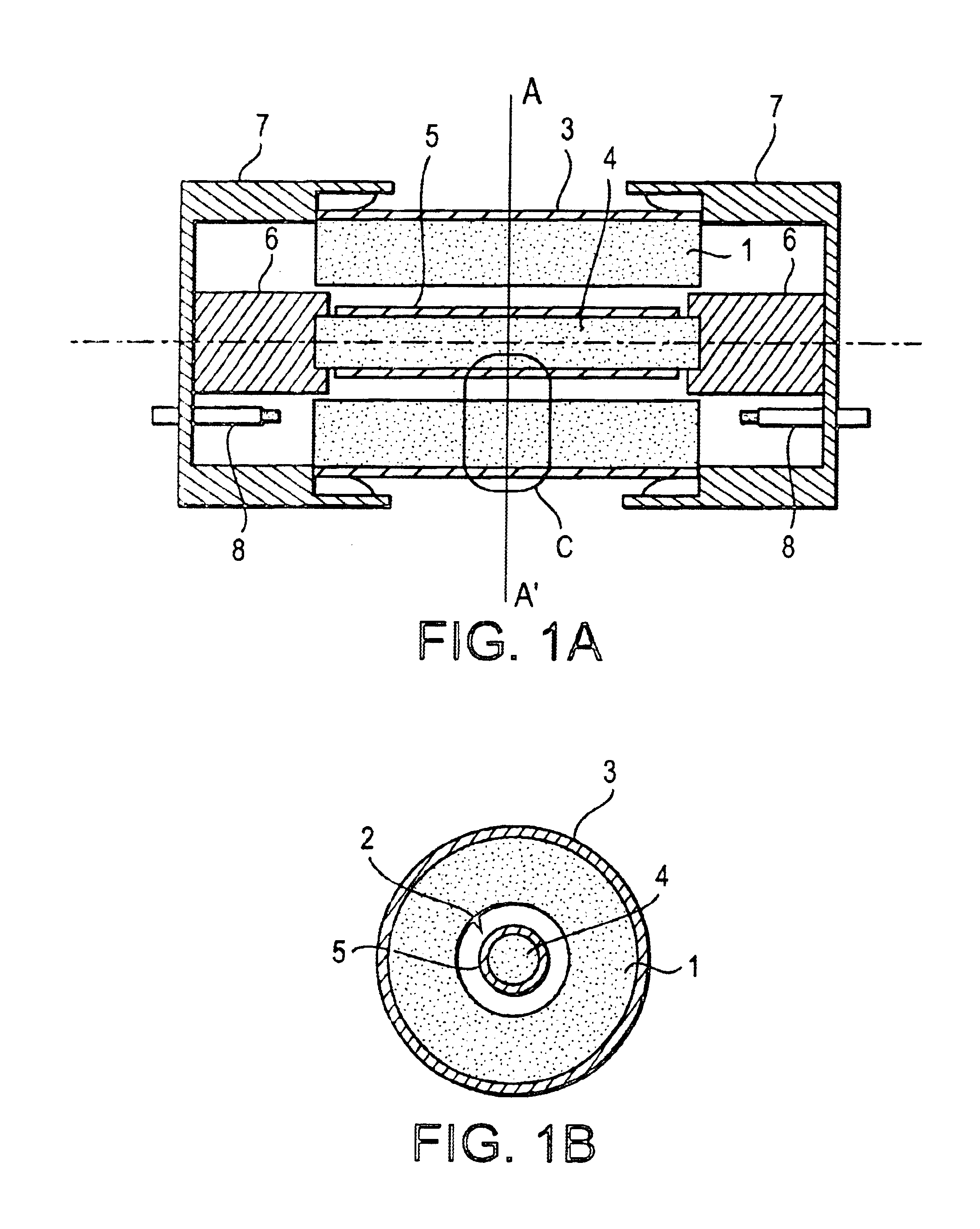
[0036]FIG. 1A is a cross-sectional view of the coaxial resonator taken along the central axis shown by the dot-dash line in the figure, and FIG. 1B is a cross-sectional view of the same coaxial resonator taken along line A-A′ of FIG. 1A. The coaxial resonator includes a tubular dielectric block 1, an outer conductor 3 formed on an outer periphery of the dielectric block 1, and an inner conductor 5 formed on a lateral face of a cylinder element 4. The cylinder element 4 is held at its ends by cap-shaped holding members 6 so as to be received within the hole 2 in the dielectric block 1. The coaxial resonator further includes outer frames 7 attached to the ends of the dielectric block 1 for securing the holding members 6. The outer frames 7 include probes 8 which extend toward the cylinder element 4 so as to provide an input / output unit.

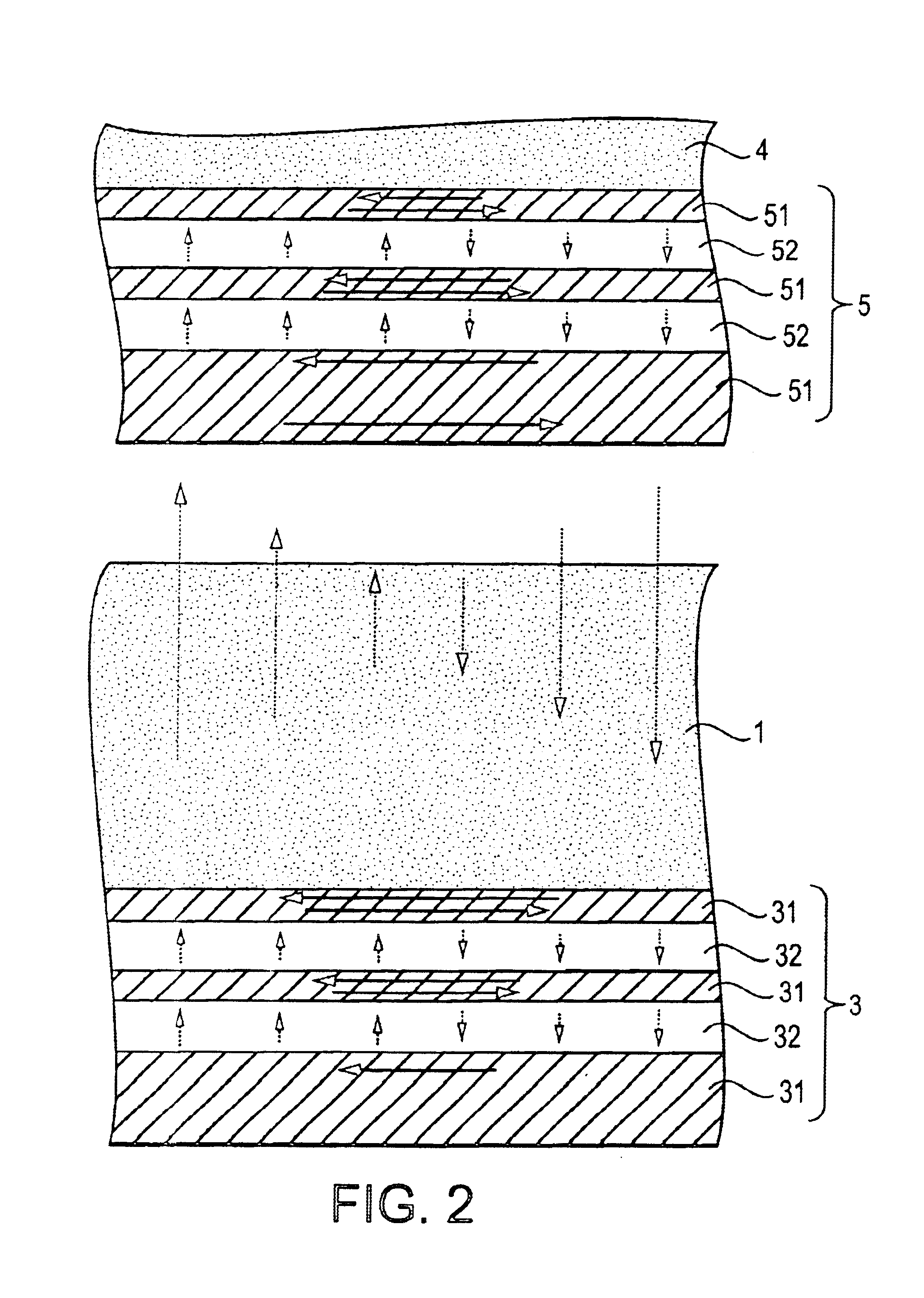
[0037]FIG. 2 is an enlarged cross-secti...

second embodiment

[0056]A coaxial resonator according to the present invention is described with reference to FIGS. 3A and 3B.

[0057]FIG. 3A is a cross-sectional view of the coaxial resonator taken along the central axis shown by the dot-dash line, and FIG. 3B is a cross-sectional view of the same coaxial resonator taken along line A-A′ of FIG. 3A. The coaxial resonator includes a tubular dielectric block 1, an outer conductor 3 formed on an outer periphery of the dielectric block 1, and an inner conductor 5 formed on a lateral face of a cylindrical shaft 4. The cylindrical shaft 4 is held by a short-circuit holding member 9 so as to be received within the hole 2 in the dielectric block 1. The short-circuit holding member 9 also conductively connects the inner conductor 5 formed on the outer surface of the cylindrical shaft 4 and the outer conductor 3 formed on the outer surface of the dielectric block 1. In this way, short-circuiting the ends of the inner conductor 5 allows the coaxial resonator acco...

fourth embodiment

[0060]FIG. 5 is a cross-sectional view of a coaxial resonator according to the present invention. As is apparent from comparison with that shown in FIGS. 4A and 4B, a non-conducting element 13 made of a material such as resin having low permittivity or high permittivity is filled in a gap between the cylindrical shaft 4 and the dielectric block 1. This structure maintains a fixed positional relationship between the cylindrical shaft 4 and the dielectric block 1, preventing a change in characteristics due to relative displacement of these components.


PUM


Abstract

A coaxial resonator according to an embodiment of the invention includes a tubular dielectric block, an inner conductor having a thin-film, multi-layer electrode structure, which is formed on an outer surface of a cylindrical shaft received in the hole of the tubular dielectric block, and an outer conductor formed on an outer surface of the tubular dielectric block. The cylindrical shaft is inserted into the hole in the dielectric block, and is held by a holding member and an outer frame.

Description

BACKGROUND OF THE INVENTION[0001]1. Field of the Invention[0002]The present invention relates to a dielectric resonator, a dielectric filter, and a dielectric duplexer of the type comprising a dielectric block and electrodes formed of conductive films which are formed on internal and / or external surfaces of the dielectric block, and to a communication device using the same.[0003]2. Description of the Related Art[0004]In general, a dielectric resonator for use mainly in the microwave band includes a prism-shaped or cylindrical dielectric block having a through-hole coaxially formed therein, an inner conductor formed on an inner surface of the through-hole, and an outer conductor formed on an outer surface of the dielectric block, so as to operate as a dielectric coaxial resonator. Another form of dielectric resonator includes a rectangular dielectric block having a plurality of through-holes formed therein, an inner conductor formed on an inner surface of each of the through-holes, a...

Claims


Application Information

Patent Timeline
Patent Type & Authority Patents(United States)
IPC IPC(8): H01P7/04H01P1/20H01P1/205H01P1/213
CPCH01P7/04H01P1/2056
Inventor ABE, SHINHIDAKA, SEIJIOKAJIMA, SHINGO
Owner MURATA MFG CO LTD
Why Eureka
Try Eureka