Hydraulic puller

a technology of hydraulic puller and seat, which is applied in the direction of metal-working equipment, metal-working equipment, manufacturing tools, etc., can solve the problems of reducing the working efficiency of the conventional hydraulic puller, inconvenience for users, and inability to easily and conveniently rotate the sea

Inactive Publication Date: 2005-05-24
HOUG WEN CHENG
View PDF4 Cites 48 Cited by
  • Summary
  • Abstract
  • Description
  • Claims
  • Application Information

AI Technical Summary

Benefits of technology

[0006]The primary objective of the present invention is to provide a hydraulic puller, wherein the operation shaft and the urging unit are moved to press the wheel axle rapidly by control of the oil control device, so that the hydraulic puller can be used to clamp the wheel rim and the wheel axle easily and rapidly, thereby facilitating the user detaching the wheel rim from the wheel axle.
[0007]Another objective of the present invention is to provide a hydraulic puller, wherein the operation handle of the pump has an adjustable length, so as to fit users of different statures, thereby enhancing the versatility of the hydraulic puller.
[0008]A further objective of the present invention is to provide a hydraulic puller, wherein the operation plate can be rotated by the user's hand to rotate and lift the clamping device so as to control operation of each of the claws, thereby facilitating the user operating the hydraulic puller.
[0009]A further objective of the present invention is to provide a hydraulic puller, wherein the oil control device is built in the inside of the hydraulic puller, thereby preventing the user from misadjusting the oil path so as to protect the hydraulic puller.

Problems solved by technology

However, the support seat cannot be rotated easily and conveniently, thereby causing inconvenience to the user when operating the conventional hydraulic puller.
In addition, the oil control device is mounted on an outside of the conventional hydraulic puller, so that the user easily misadjusts the oil path of the oil control device, thereby wearing the conventional hydraulic puller.
Further, the oil path of the oil control device is operated slowly, so that the wheel rim and the wheel axle cannot be positioned easily and rapidly, thereby decreasing the working efficiency of the conventional hydraulic puller.

Method used


Image

  • Hydraulic puller
  • Hydraulic puller
  • Hydraulic puller

Examples


Embodiment Construction

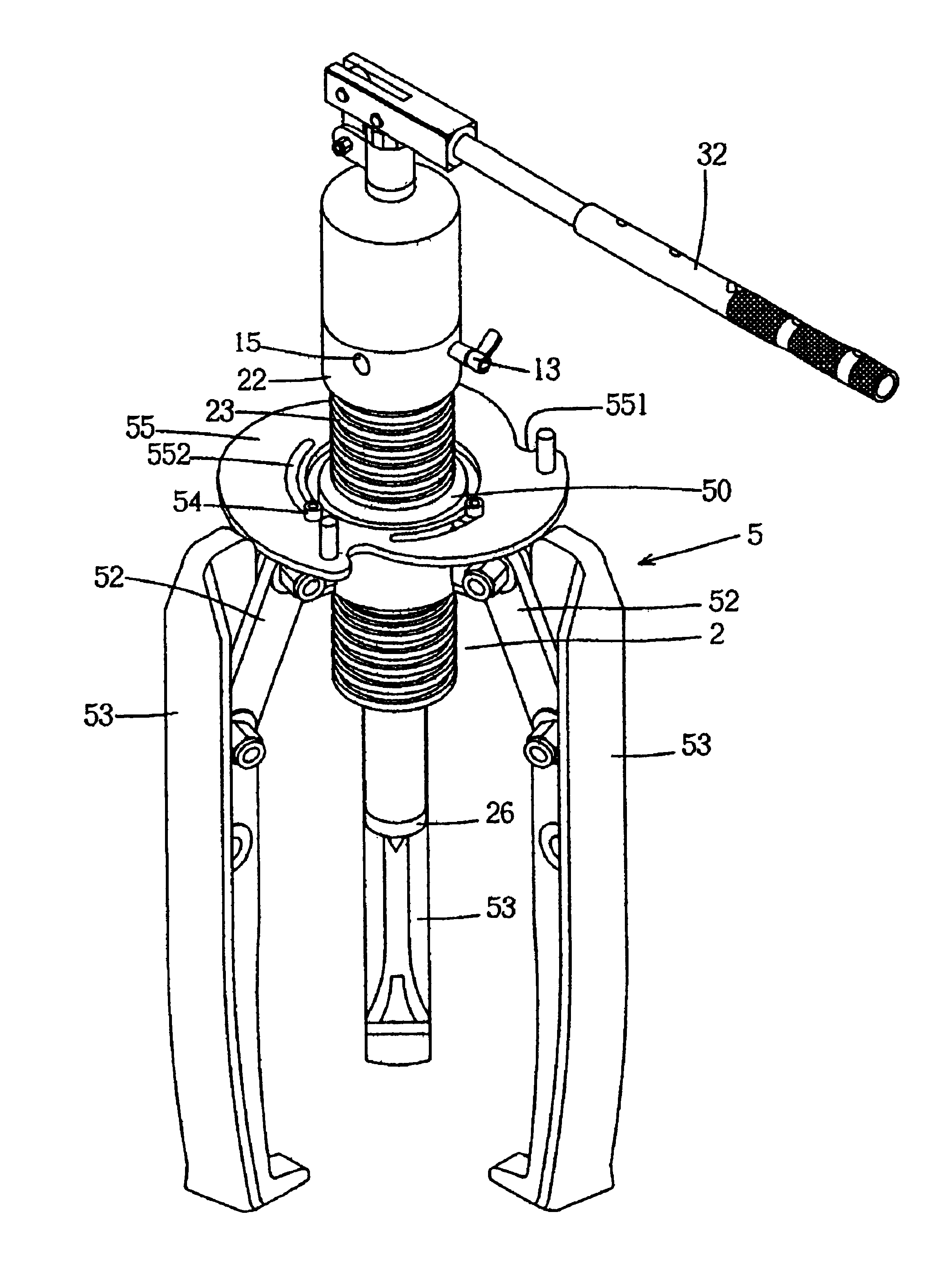
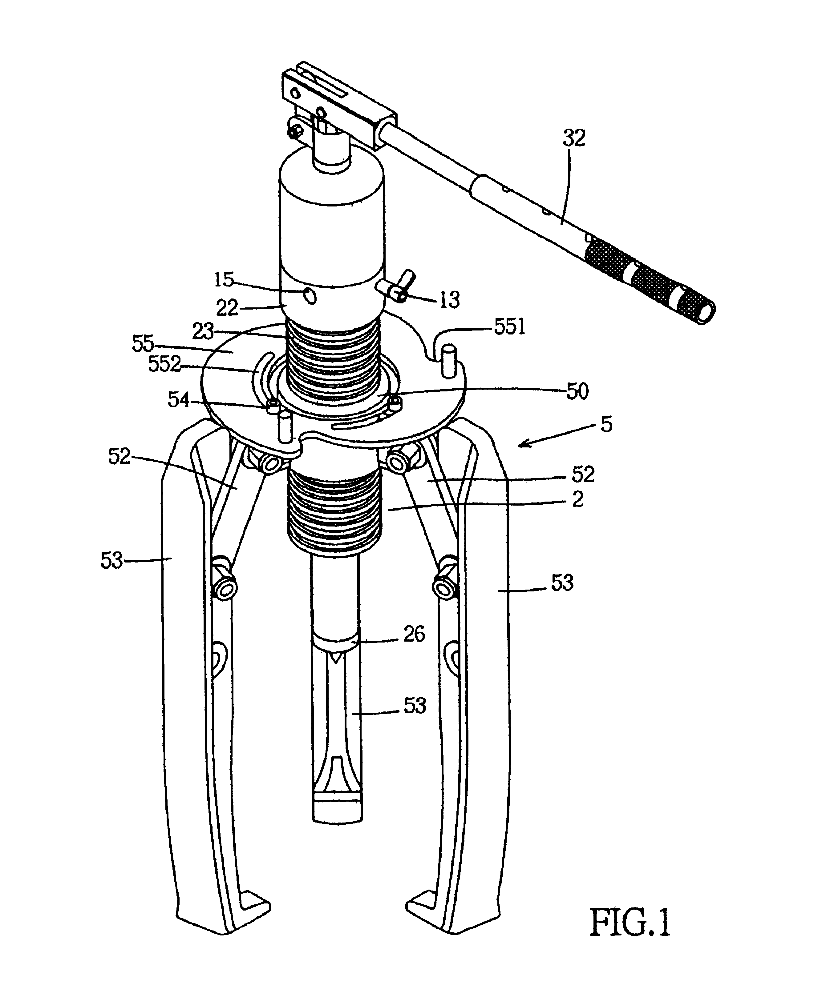
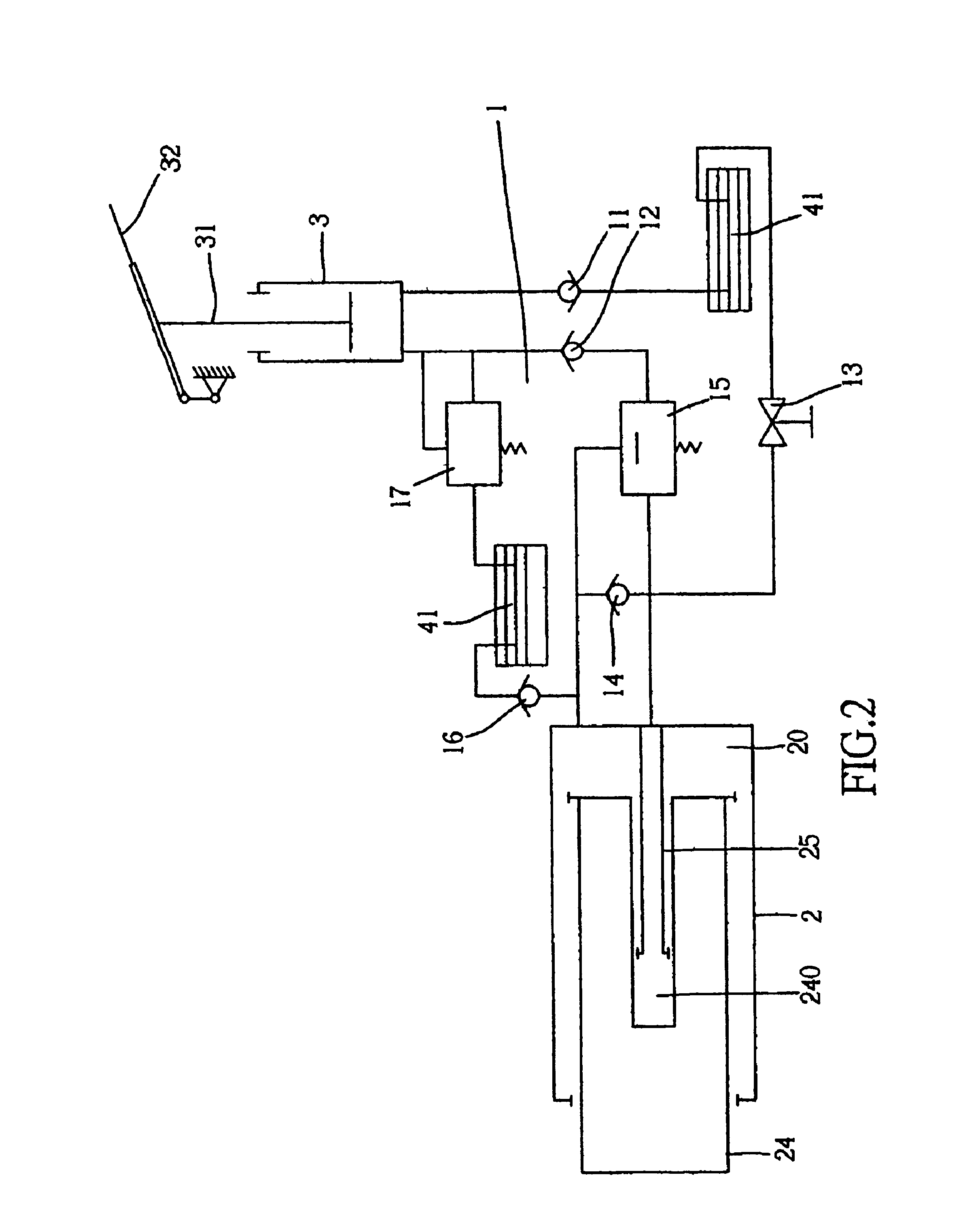
[0034]Referring to the drawings and initially to FIGS. 1-7, a hydraulic puller in accordance with the preferred embodiment of the present invention comprises an oil control device 1, a hydraulic cylinder 2, a pump 3, an oil tank 4, and a clamping device 5.

[0035]The hydraulic cylinder 2 has an inner wall formed with an oil chamber 20 for receiving an operation shaft 24 and an oil guide tube 25. The operation shaft 24 is movably mounted in the oil chamber 20 of the hydraulic cylinder 2 and has a lower end provided with an urging unit 26. The hydraulic cylinder 2 has an upper section 22 formed with a central hole 228, the operation shaft 24 has an upper end formed with an oil chamber 240, and the oil guide tube 25 has an upper end mounted in the central hole 228 of the upper section 22 of the hydraulic cylinder 2 and a lower end movably mounted in the oil chamber 240 of the operation shaft 24. A spring 242 is mounted on the operation shaft 24 and has a first end secured on a top of the...


PUM

PropertyMeasurementUnit
lengthaaaaaaaaaa
pressureaaaaaaaaaa
timeaaaaaaaaaa

Abstract

A hydraulic puller includes a hydraulic cylinder, a pump, an oil tank, and a clamping device. The clamping device includes a support seat, a plurality of pivot plates, a plurality of connecting plates, a plurality of claws, and an operation plate. Thus, the operation plate can be rotated by the user's hand to rotate and lift the clamping device so as to control operation of each of the claws, thereby facilitating the user operating the hydraulic puller.

Description

BACKGROUND OF THE INVENTION[0001]1. Field of the Invention[0002]The present invention relates to a hydraulic puller, and more particularly to a hydraulic puller that can be used to clamp the wheel rim and the wheel axle easily and rapidly, thereby facilitating the user detaching the wheel rim from the wheel axle.[0003]2. Description of the Related Art[0004]A conventional hydraulic puller can be used to detach the wheel rim from the wheel axle and comprises a hydraulic cylinder having a lower section formed with an outer thread, and a clamping device including a support seat formed with an inner thread screwed on the outer thread of the hydraulic cylinder, and a plurality of claws each pivotally mounted on the support seat and each having a distal end formed with a hook hooked on the wheel rim. Thus, the support seat can be rotated by the user's hand to rotate and lift the clamping device to control operation of each of the claws. The conventional hydraulic puller also comprises an o...

Claims


Application Information

Patent Timeline
Patent Type & Authority Patents(United States)
IPC IPC(8): B25B27/02
CPCB25B27/026Y10T29/5383Y10T29/5387
Inventor HOUG, WEN-CHENG
Owner HOUG WEN CHENG
Why Eureka
Try Eureka