Stripper plate retention system

a technology of stripper plate and retention system, which is applied in the direction of manufacturing tools, saw chains, metal working apparatuses, etc., can solve the problems of stripper plate being pulled out of place, inconvenient to interchange punch and die combinations, and not providing completely satisfactory performan

Inactive Publication Date: 2005-05-24
WILSON TOOL INT
View PDF25 Cites 23 Cited by
  • Summary
  • Abstract
  • Description
  • Claims
  • Application Information

AI Technical Summary

Benefits of technology

[0015]U.S. Pat. No. 6,082,516 discloses a stripper plate release mechanism comprising a locking ring with three arcuate grooves having radially-increasing dimension and three locking clips which are circumferentially fixed relative to the locking ring. The locking clips engage the stripper plate. Upon rotation of the locking ring, the locking clips ride in the arcuate grooves which act as camming surfaces and open the locking clips, thereby releasing the stripper plate. As with certain other prior art stripper plate release mechanisms, this mechanism requires a rotation step to release the stripper plate. It would be desirable to provide a stripper plate release mechanism that does not require rotation or substantial manipulation to remove and replace the stripper plate.

Problems solved by technology

However, since the size and shape of the stripper plate hole must coincide closely with that of the punch tip, each punch guide of the nature is limited to use with a matching punch.
Consequently, it may be inconvenient to interchange punch and die combinations, since the operator must change not only the die and punch, but the punch guide as well.
These spring clip structures, however, have not provided completely satisfactory performance.
When this occurs, the stripper plate may be pulled out of place and damage may result to the workpiece and to the stripper plate.
Down time may also be a problem.
Finally, these clips tend to weaken with continued use, potentially aggravating the noted problems.
In some cases, the manipulation of these small parts may be more difficult and time consuming than is preferred.
Such snap rings may neither be strong enough nor reliable enough to securely lock the stripper plate in position.
Such spring clips may not be strong enough for large diameter punch sets and may weaken with repeated use.
This rotatable retaining ring and stripper plate assembly includes a number of small parts, such as pins and springs, that add complexity and fabrication costs.
Moreover, the stripper plate retaining ring itself is removed when the stripper plate is released, thus potentially risking its loss or damage if dropped.
This is less than ideal in terms of ease of stripper plate removal and replacement.

Method used


Image

  • Stripper plate retention system
  • Stripper plate retention system
  • Stripper plate retention system

Examples


Embodiment Construction

[0038]The following detailed description is to be read with reference to the drawings, in which like elements in different drawings have like reference numerals. The drawings, which are not necessarily to scale, depict selected embodiments and are not intended to limit the scope of the invention. Skilled artisans will recognize that the examples provided herein have many useful alternatives that fall within the scope of the invention.

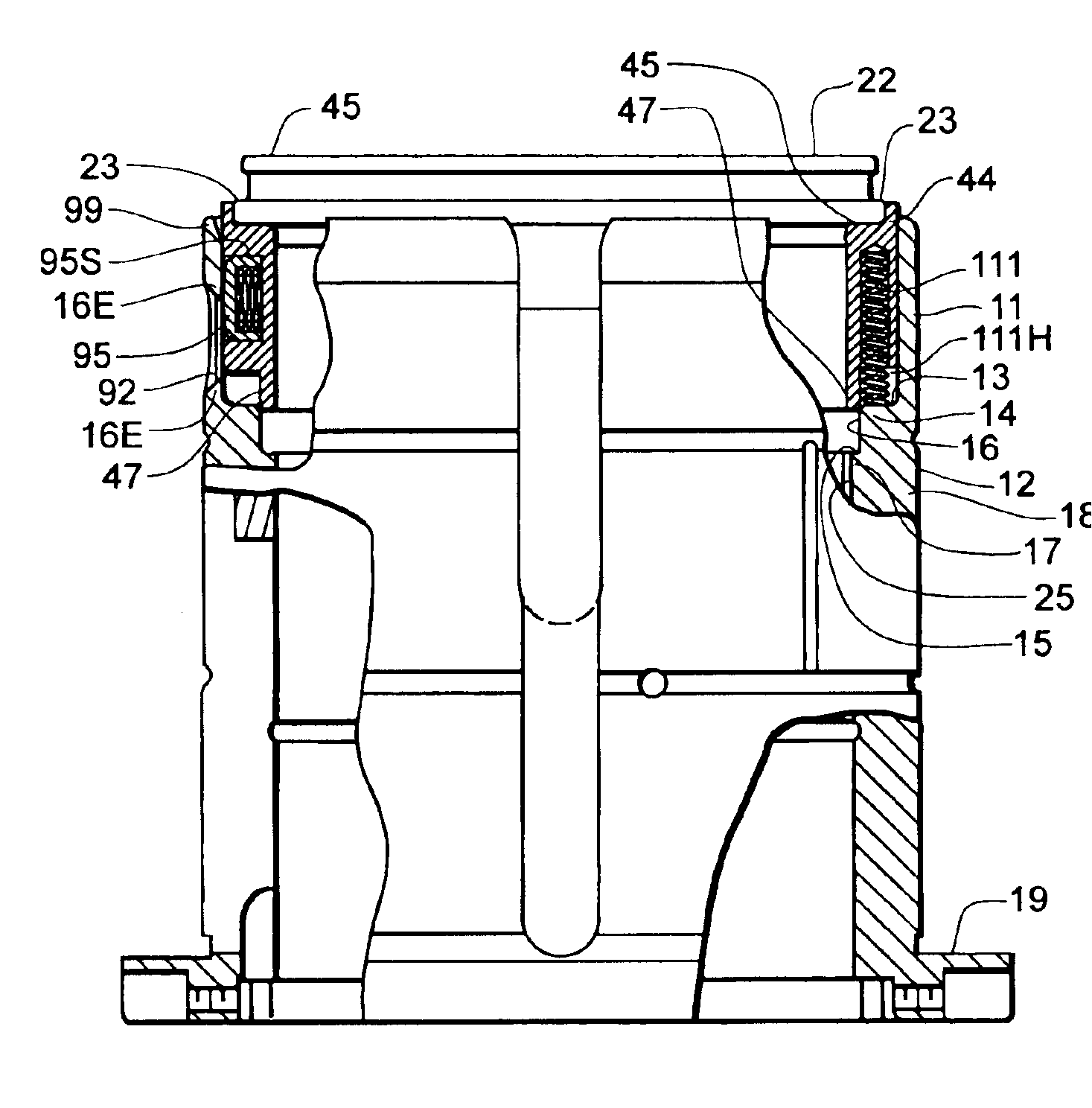
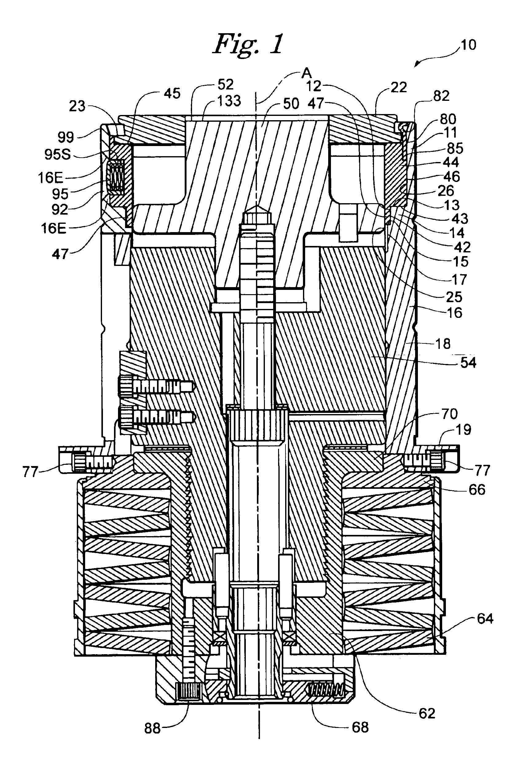
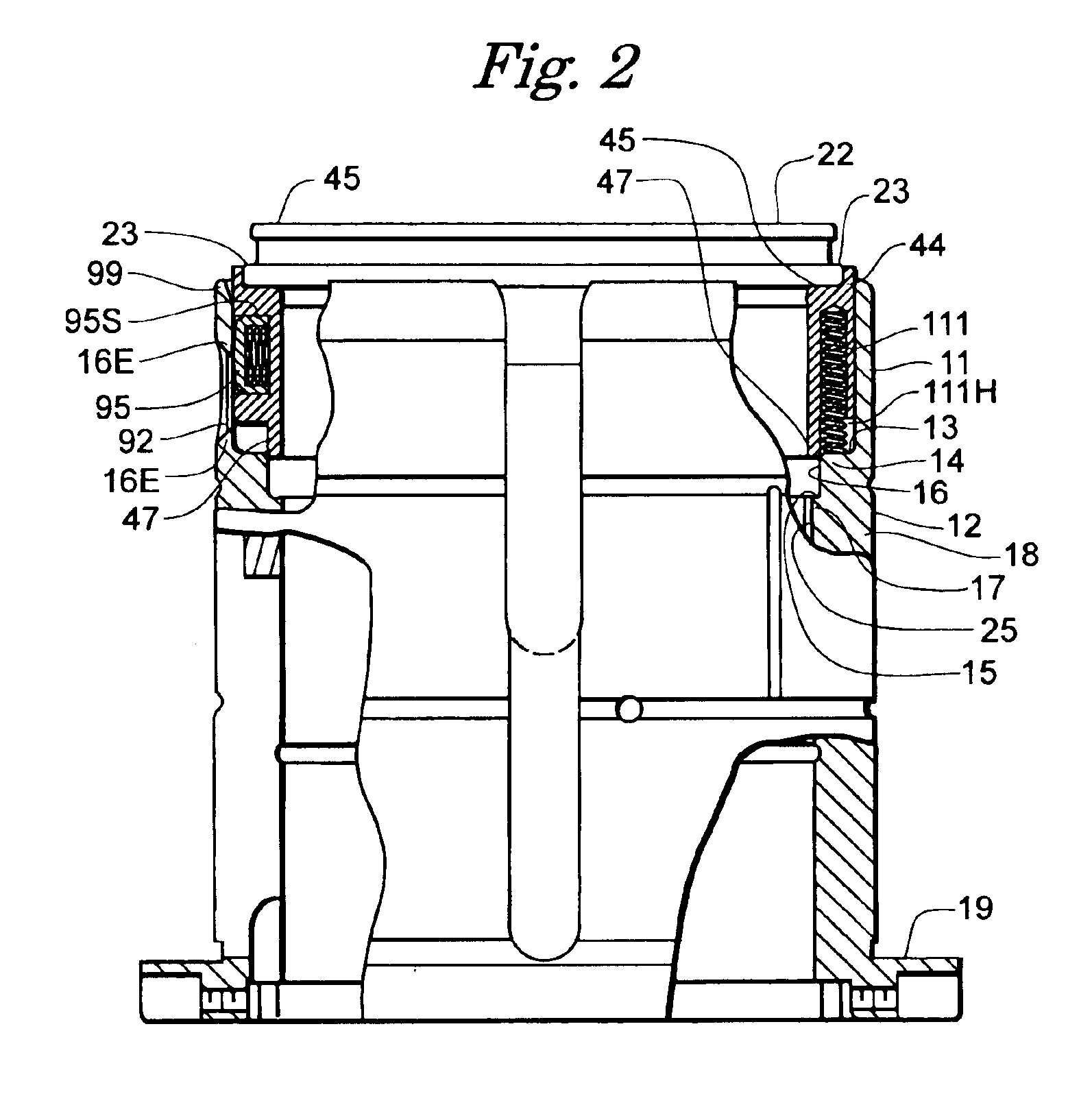
[0039]FIG. 1 illustrates a punch assembly 10 comprising a stripper plate retention system in accordance with one embodiment of the present invention. The illustrated punch assembly 10 generally includes a punch 50, a punch guide 16, a stripper plate 22, a stripper plate guide 44, a punch holder 54, and a punch driver 62. The punch 50 is centrally disposed and has a punch tip 52 adapted to extend through an opening 13 in the stripper plate 22. The illustrated punch assembly 10 includes a punch spring 64 surrounding the punch driver 62. The punch spring 6...


PUM

PropertyMeasurementUnit
diameteraaaaaaaaaa
interior diameteraaaaaaaaaa
axial movementaaaaaaaaaa

Abstract

A punch guide assembly is provided for removably carrying a stripper plate. The punch guide assembly comprises a punch guide and a stripper plate guide movable axially with respect to the punch guide. The stripper plate guide has a locked position wherein the stripper plate is secured to the punch guide assembly and an unlocked position wherein the stripper plate can be readily removed from the punch guide assembly. The stripper plate guide is resiliently biased axially toward its unlocked position yet is restrained against axial movement relative to the punch guide when in its locked position.

Description

FIELD OF THE INVENTION[0001]The present invention relates generally to punch guides, such as those used with industrial punch presses. More particularly, this invention relates to stripper plate retention assemblies for punch guides and the like.BACKGROUND OF THE INVENTION[0002]Multiple-station turret punch machines can provide up to 72 different punch stations for use in conjunction with a like number of opposing dies. In such a machine, each punch station operates as a punch set holder for a removable punch set that includes a centrally-disposed punch surrounded by a punch guide and biased by a punch spring. Even with the flexibility afforded by a 72-station machine, the operator may wish to change some or all of the punch set and die combinations from time to time. For instance, the operator may wish to utilize a different punch tip shape or size in a punch set. It is desirable to minimize the time required, and make it simple, to change the punch and die components, so that down...

Claims


Application Information

Patent Timeline
Patent Type & Authority Patents(United States)
IPC IPC(8): B21D45/00B21D28/34B21D28/00B21D45/08
CPCB21D45/006Y10T83/9307Y10T83/9423Y10T83/9464Y10T83/9476Y10T83/2159
Inventor ROSENE, RONALD G.TIMP, RICHARD L.ROBINSON, VERLON
Owner WILSON TOOL INT
Why Eureka
Try Eureka