Muntin grid assembly and mounting system

a technology of mounting system and grid, which is applied in the direction of manufacturing tools, building scaffolds, rod connections, etc., can solve the problems of only practical methods, difficult to align the grid with its intended pattern, and reduce the vision area of windows or doors

Inactive Publication Date: 2005-05-31
FOLSOM PETER +1
View PDF42 Cites 38 Cited by
  • Summary
  • Abstract
  • Description
  • Claims
  • Application Information

AI Technical Summary

Benefits of technology

[0036]The use of adhesives is optional for the attachment of muntin grids. Their application can be local, i.e. at intersections and / or bar ends, but more commonly, cover the whole length of contact surface of each bar of the muntin grid and the substrate.

Problems solved by technology

This method results in a structurally weaker assembly making it difficult to align the grid with its intended pattern.
However, this method is only practical when the grid profile is of a rectangular, cross-sectional box shape.
However, the width of the outer border projects into the glazing area and reduces the vision area of a window or door.
Under currently known methods the proper alignment of said free ends is difficult.
This difficulty increases when exterior and interior muntin grids are being used in combination to achieve more likeness with true divided lights.

Method used


Image

  • Muntin grid assembly and mounting system
  • Muntin grid assembly and mounting system
  • Muntin grid assembly and mounting system

Examples


Embodiment Construction

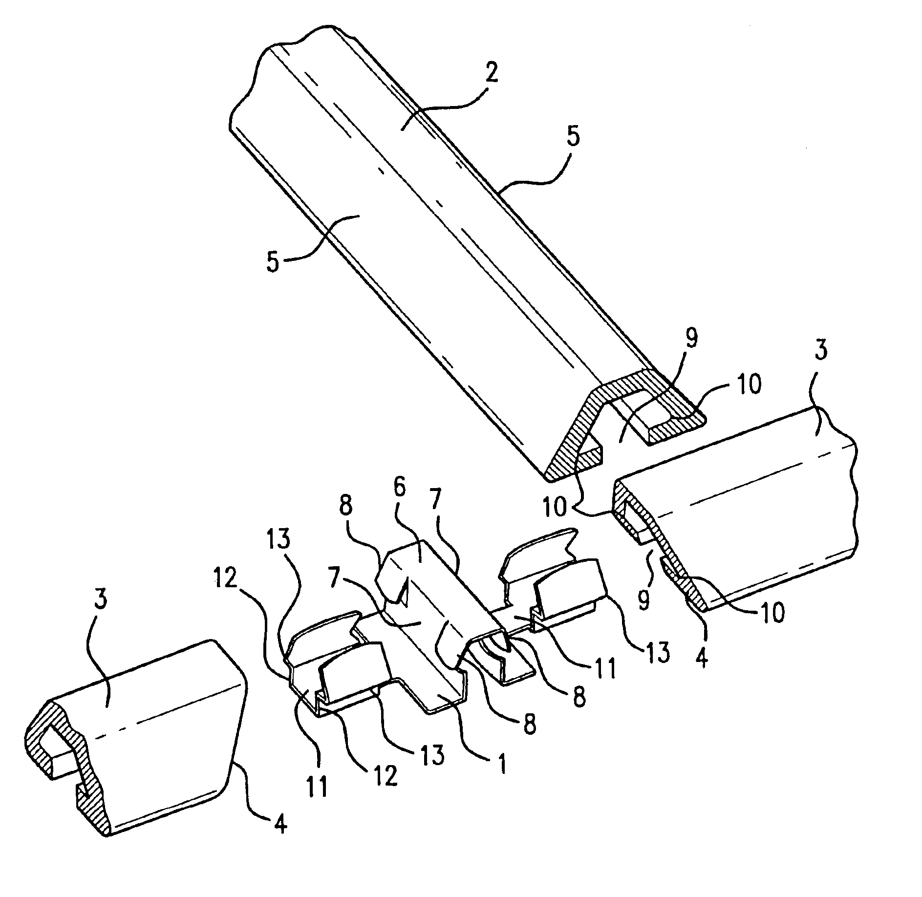
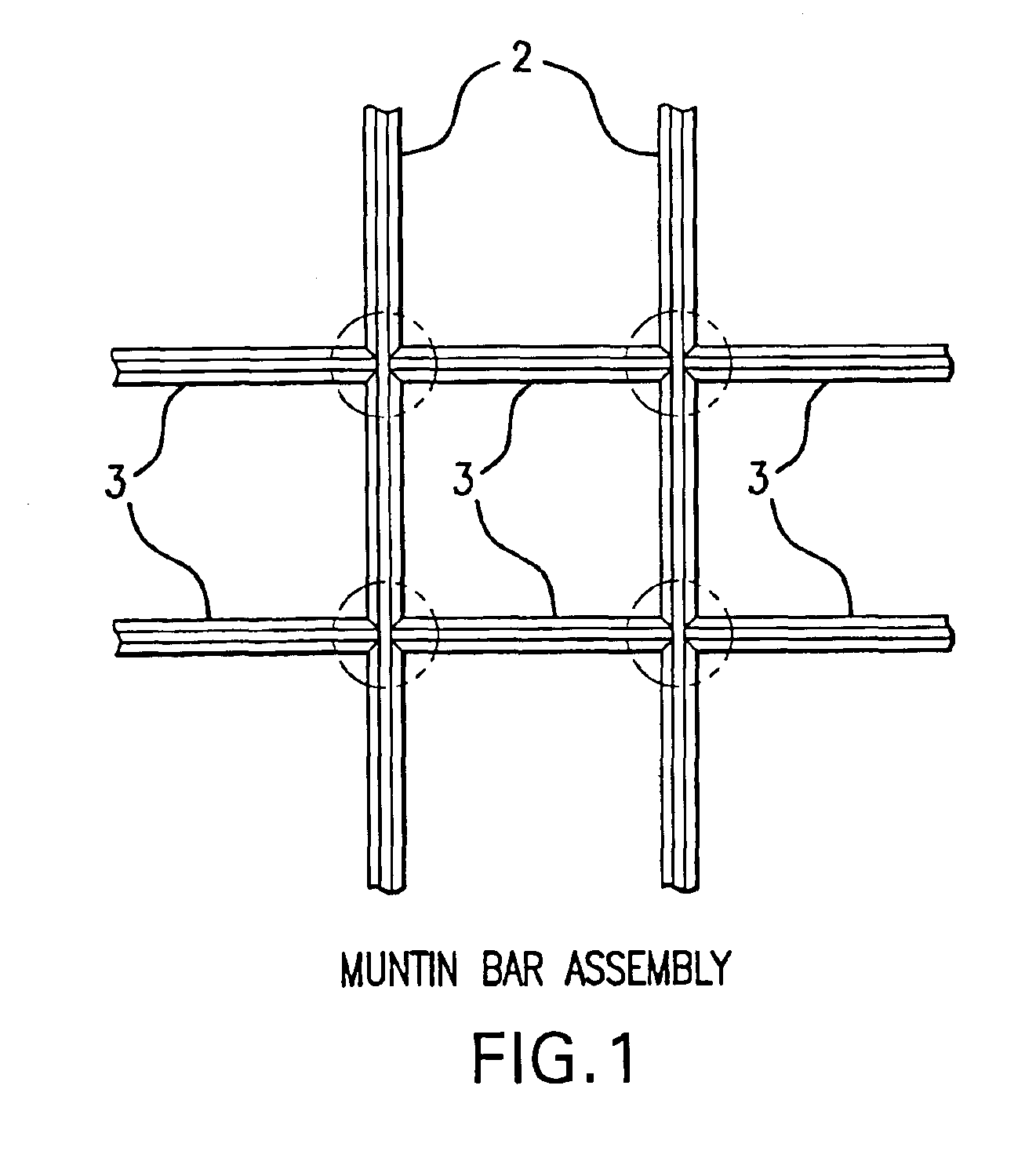
[0045]According to the present invention, and as illustrated generally in FIG. 1, there is provided an intersection clip having a spring clip element 1 for the creation of cross-shaped intersections between a continuous muntin bar 2 and two short muntin bar parts 3 positioned on opposite sides of said continuous muntin bar.

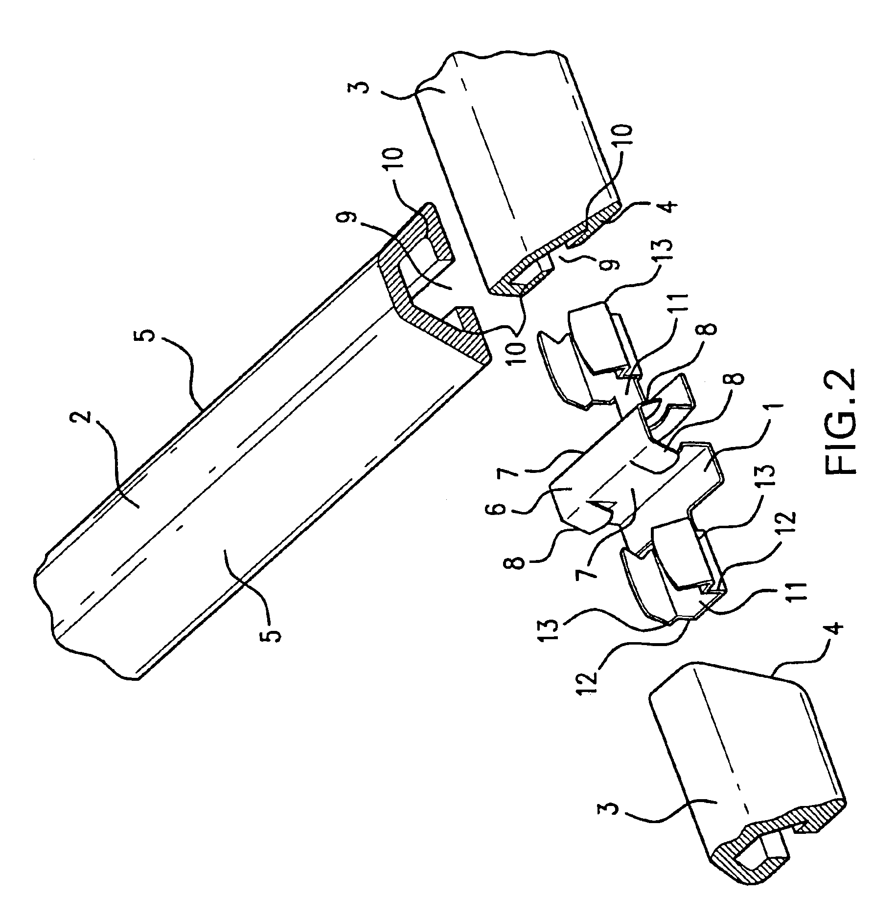
[0046]As illustrated in more detail in FIG. 2, the short muntin bar parts having at least one of its extremities 4 prepared for mating with said continuous muntin bar shape 5. The spring clip element 1, has a raised central portion 6 formed mainly by opposing surfaces 7. The opposing surfaces having wing-like extensions 8 which protrude beyond the surfaces. These wings preferably act like springs to facilitate the engagement of the central portion 6 of the intersection clip 1 into the central recess 9 of the continuous muntin bar 2.

[0047]It is preferable that the recess, 9 in the muntin bars have opposing and undercut side walls 10 to allow for a positive retentio...


PUM


Abstract

A muntin bar assembly for a window or door including a peripheral frame; a continuous surface contained within the frame; at least one continuous muntin bar and at least two discontinuous muntin bars on at least one side of the surface. The continuous muntin bar and discontinuous muntin bars both contain a continuous recessed portion on their underside and are connected together using an intersection clip having a spring-type arrangement which forms an intersection of the bars. The intersection clip has a raised central section that fits within the recessed portion of the continuous muntin bar; and further has two extensions positioned at opposite sides from the central portion which permit engagement of the discontinuous muntin bars to form the muntin assembly. An end clip is also included for attachment and alignment of the inner and outer assembly muntin bar ends and has a U-shape that fits over the edges of the surface for aligning and attaching the inner and outer assembly muntin bars.

Description

FIELD OF THE INVENTION[0001]The present invention relates to a muntin bar assembly for windows or doors, and their mounting into a frame.BACKGROUND OF THE INVENTION[0002]Muntin grids consist of lineal elements that are destined to subdivide an opening created by a perimeter frame work assembly, particularly in the context of windows and doors. Such assemblies are usually referred to as divided lights.[0003]As it is known in the art, said muntin grids traditionally formed a structural assembly with the perimeter framework, creating a multitude of openings that had to be closed by a multitude of smaller panes of glass. Surface-applied muntin grids within a perimeter framework, however, provide the advantage of using only a single glazing element to close the opening. In the case of a glazing element made from more than one pane of glazing, such as an insulating glass unit, an additional muntin grid can be installed internally in-between the panes, to create a likeness to the tradition...

Claims


Application Information

Patent Timeline
Patent Type & Authority Patents(United States)
IPC IPC(8): E06B3/00E06B3/68
CPCE06B3/685Y10T403/7194
Inventor FOLSOM, PETERSCHMIDT, HELMUT
Owner FOLSOM PETER
Why Eureka
Try Eureka