Recording apparatus

Active Publication Date: 2005-05-31
CANON KK
View PDF4 Cites 22 Cited by
  • Summary
  • Abstract
  • Description
  • Claims
  • Application Information

AI Technical Summary

Benefits of technology

[0011]With the above structure, because it is unnecessary to specially form a member for discharging static electricity from the electrostatically charged recording medium, the static electricity charged at the recording medium can be made to escape effectively from the co

Problems solved by technology

Therefore, if recording is made to a position extending beyond an edge of the sheet to achieve recording with no margin with respect to edges of the sheet, the sheet may be stained with discharged ink droplets that float around the back side of the sheet.
With this prior art str

Method used


Image

  • Recording apparatus
  • Recording apparatus
  • Recording apparatus

Examples


first embodiment

[First Embodiment]

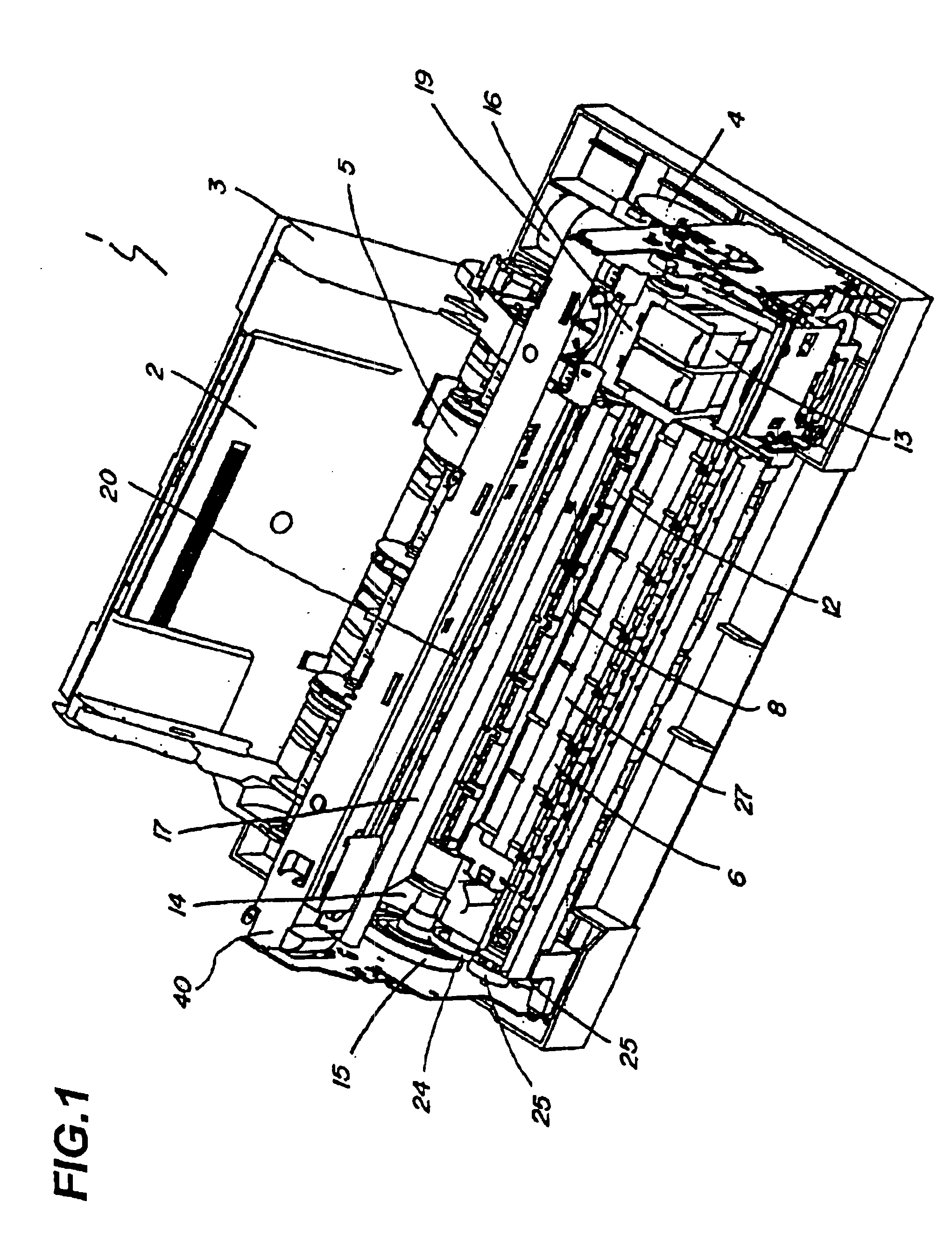
[0022]Hereinafter, a recording apparatus according to the first embodiment will be described with reference to FIG. 1 through FIG. 7. It is to be noted that in this embodiment an inkjet printer is exemplified as a recording apparatus for description.

[0023]First, an outline of the entire structure of the apparatus and operation of recording with no margin will be described.

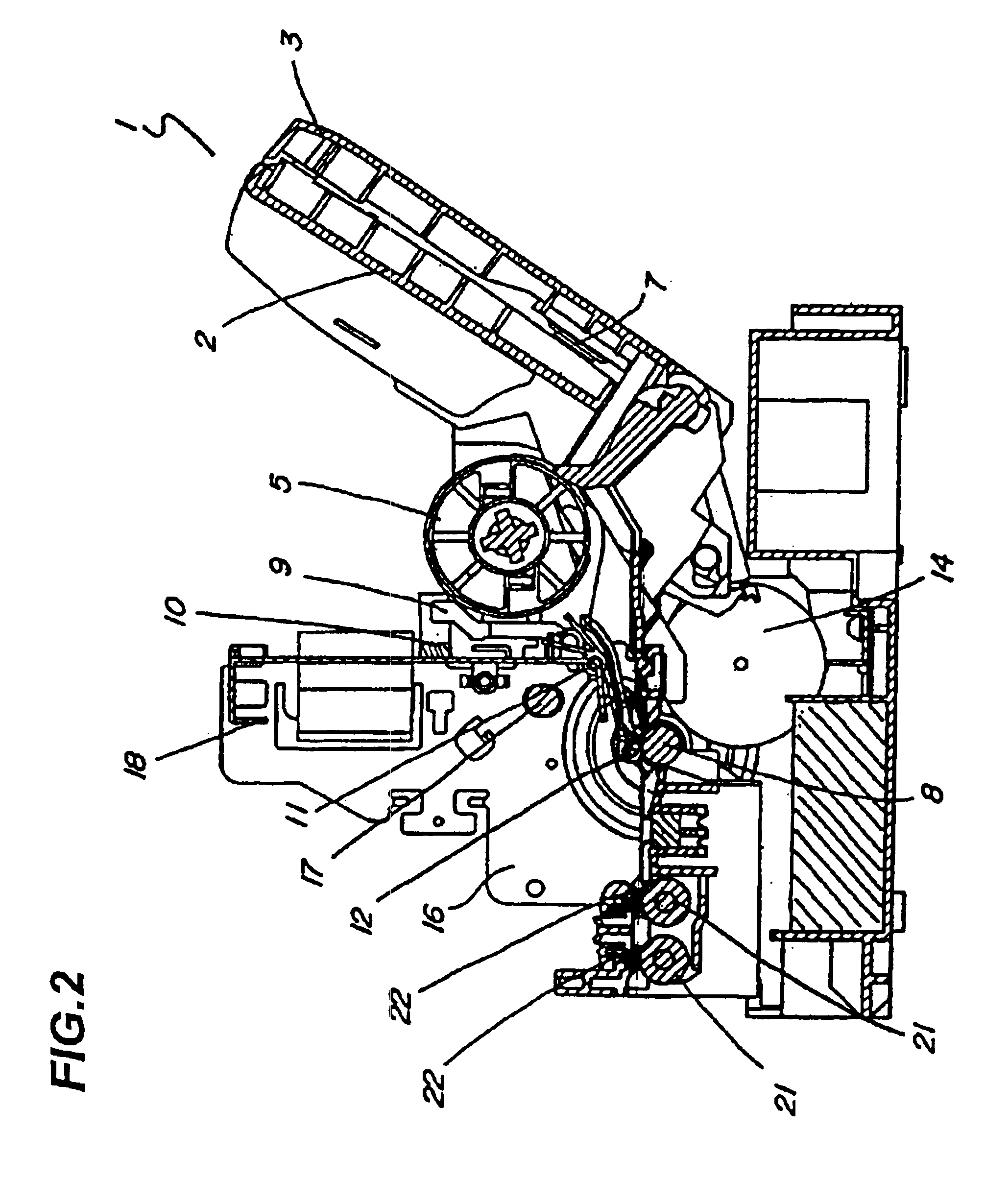
[0024]As shown in FIG. 1, a pressing plate 2 of a feeding apparatus 1 is pivotally supported by a feeding apparatus frame 3, and sheet bundles are stacked on a top face of the pressing plate 2. During sheet feeding, a feeding roller 5 rotates in association with a feeding motor 4 as a drive source, and the pressing plate 2 moves pivotally toward the feeding roller 5 with the aid of a pressing plate spring 7 (see FIG. 2) to press the sheet bundle to the feeding roller 5. When the feeding roller 5 further rotates, only the topmost sheet of the sheet bundle is separated and fed downstream.

[0025]The s...


PUM


Abstract

The present invention relates to a recording apparatus for recording an image by discharging an ink, and including a recording head capable of recording to at least one edge of recording medium without any margin, a receiving portion for receiving ink droplets discharged at a position extending beyond the edge of the recording medium, and a conveyance rotary body located at an upstream side of the receiving portion with respect to a conveyance direction of the recording medium. The conveyance rotary body is made conductive to an apparatus body.

Description

BACKGROUND OF THE INVENTION[0001]1. Field of the Invention[0002]This invention relates to a recording apparatus capable of recording up to at least one edge of a recording medium with no margin.[0003]2. Related Background Art[0004]Referring to FIG. 8 and FIG. 9, a prior art recording apparatus will be described. Conventionally, in a recording apparatus capable of recording with no margin at edges of a recording medium, such as a sheet or the like, an ink-jet recording apparatus capable of recording with no margin has been known to have a structure in which an opening is formed in a sheet passing surface of a platen 6 for holding the sheet at a recording position, in which a recess 26 made of vertical surfaces and a bottom surface is formed below the opening, and in which ink absorbing materials (hereinafter, referred to as “platen ink absorbing material 27”) are provided in the recess 26. Such a concrete structure is disclosed in JP-A-2000-118058.[0005]With this inkjet recording app...

Claims


Application Information

Patent Timeline
IPC IPC(8): B41J11/00B41J11/06B41J11/02B41J2/185B41J2/18B41J13/076B65H5/00B65H5/06
CPCB41J11/06B41J11/0065
Inventor NIIKURA, TAKEJIOGASAWARA, SEIJI
Owner CANON KK
Why Eureka
Try Eureka