Cut off and strike off mechanism for a paving machine

a technology of cutting and striking off and paving machines, which is applied in the direction of roads, roads, construction, etc., can solve the problems of restricting the position of the auger

Inactive Publication Date: 2005-05-31
VT LEEBOY INC
View PDF6 Cites 11 Cited by
  • Summary
  • Abstract
  • Description
  • Claims
  • Application Information

AI Technical Summary

Benefits of technology

[0010]The present invention satisfies the above-described need for an improved auger / cut off assembly by providing an auger / cut off assembly consisting of an auger mechanism and a cut off mechanism. The auger mechanism consists of a auger support member for supporting an auger for rotation about an axis. The cut off mechanism consists of at least one concave cut off panel that is rotated by means of an actuator about the axis of the auger between an open strike off position and a closed cut off position. Because the concave cut off panel closely conforms to a portion of the circumference of the auger, the auger / cut off assembly allows low ground clearance.

Problems solved by technology

The swinging cut off plate below the auger required additional ground clearance for its operation and thereby restricted how low the auger could be positioned.

Method used


Image

  • Cut off and strike off mechanism for a paving machine
  • Cut off and strike off mechanism for a paving machine
  • Cut off and strike off mechanism for a paving machine

Examples


Embodiment Construction

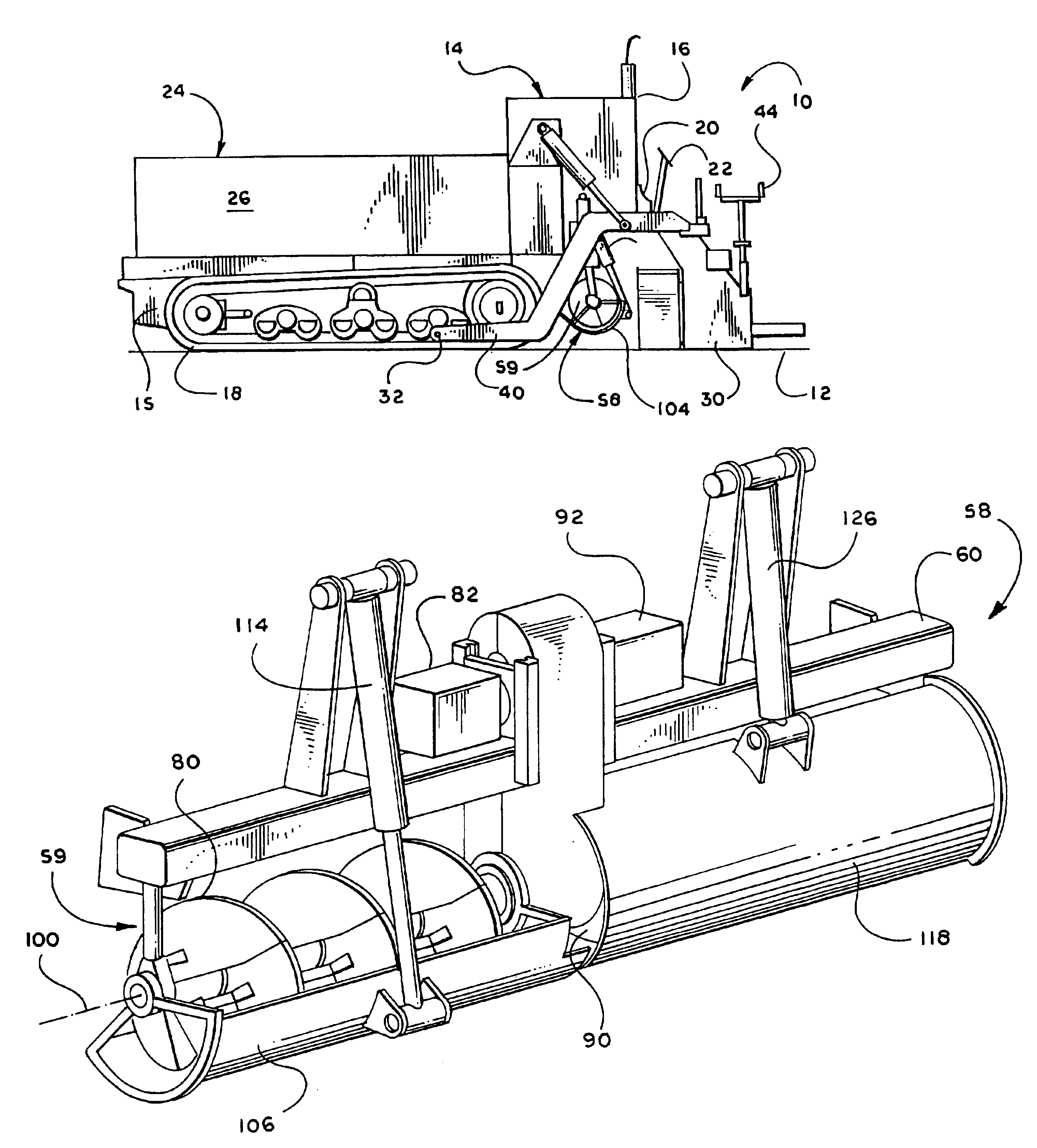
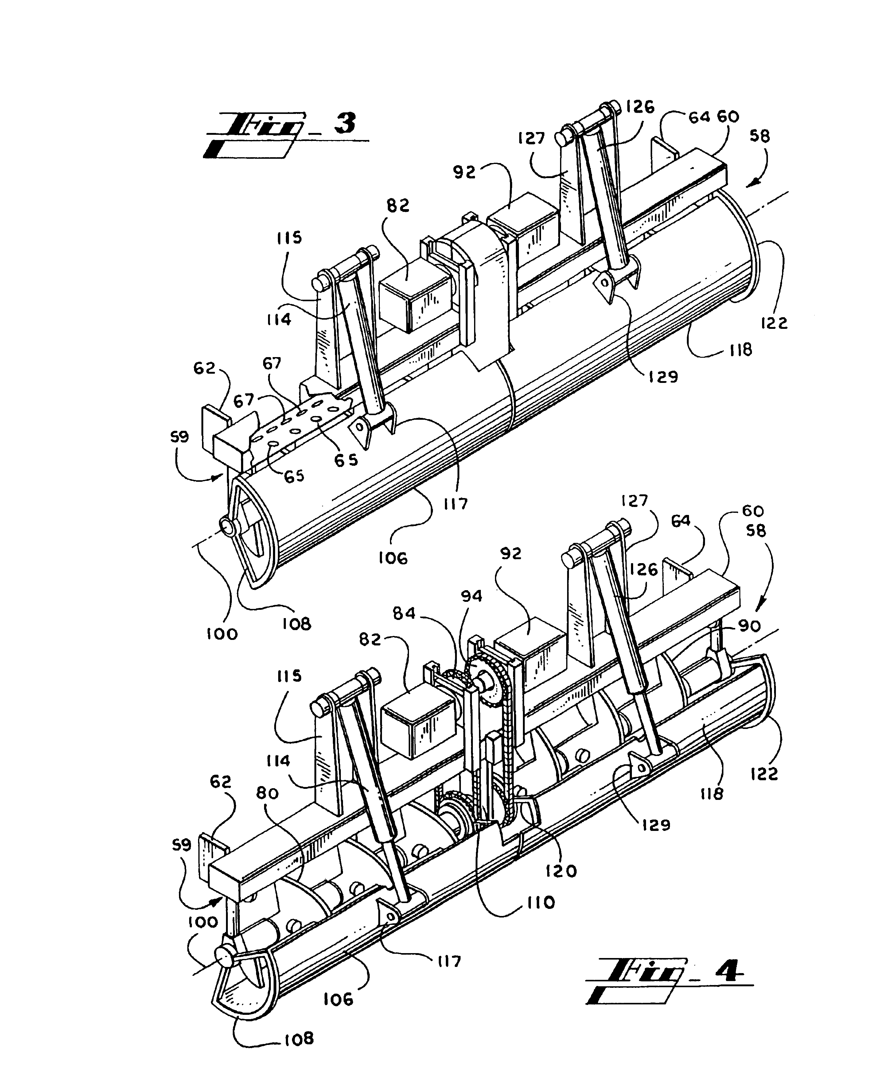
[0022]The present invention is an auger / cut off assembly for a floating screed paver. The auger / cut off assembly comprises an auger mechanism and a cut off mechanism. The auger mechanism consists of an auger support member attached to the floating screed paver which supports an auger for rotation about an axis. The cut off mechanism consists of at least one concave cut off panel that is rotated by means of an actuator about the axis of the auger between an open strike off position and a closed cut off position. In one embodiment, the auger mechanism consists of two independently controlled augers, and the cut off mechanism consists of two concave cut off panels that are independently rotated by means of independent actuators about the axis of the augers between an open strike off position and a closed cut off position.

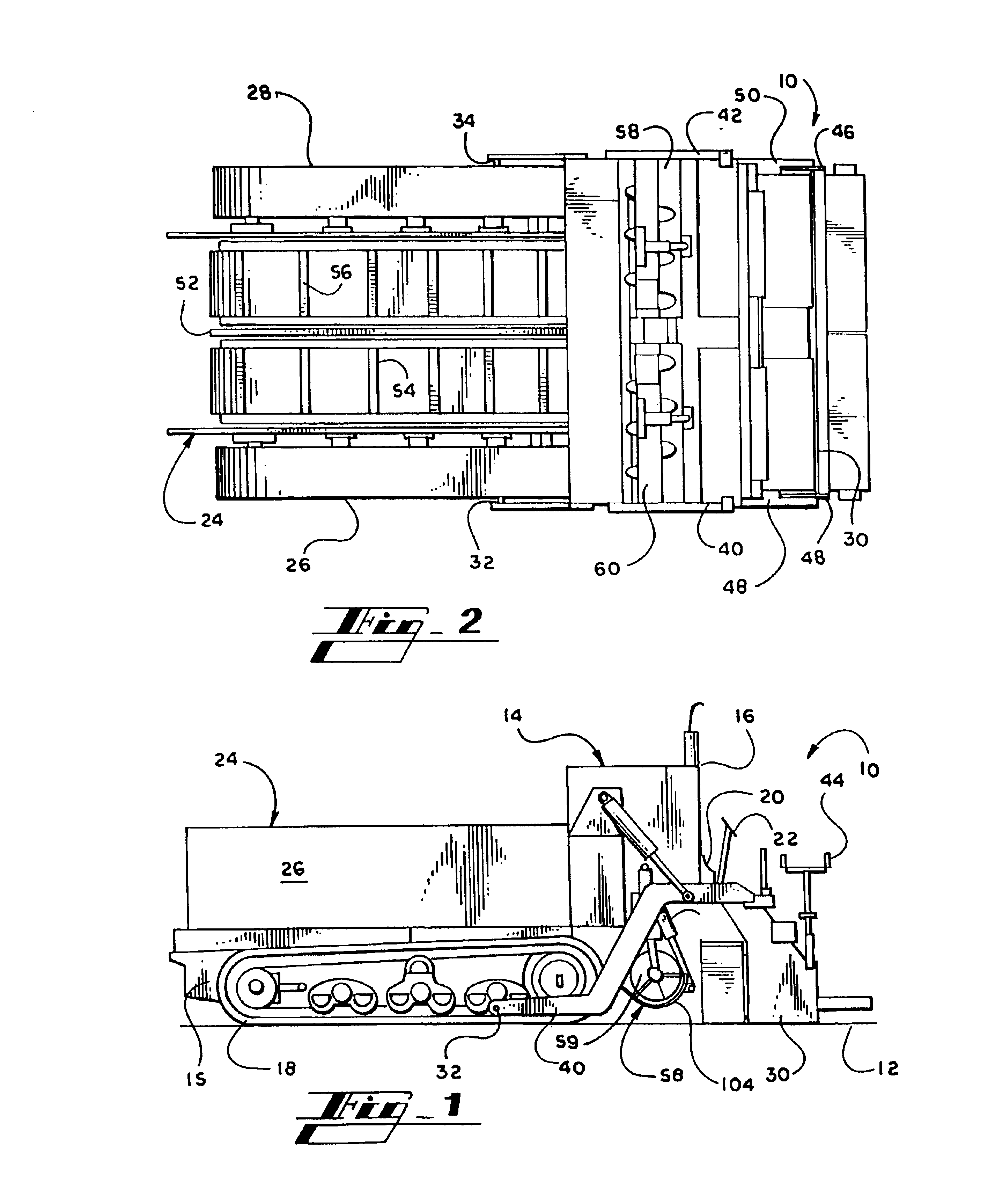
[0023]Turning to the figures, FIG. 1 is a side elevation view of a floating screed asphalt paver 10 in accordance with the present invention. The floating screed paver...


PUM


Abstract

An auger / cut off assembly for a floating screed asphalt paver. The auger / cut off assembly consists of an auger mechanism with an axis of rotation and a cut off mechanism. The cut off mechanism has a concave cut off panel that rotates about the axis of the auger mechanism from an open strike off position to a closed cut off position. Because the concave cut off panel closely conforms to a portion of the circumference of the auger mechanism, the cut off mechanism provides for low ground clearance. The concave cut off panel serves the dual function of striking off the paving material when in the open strike off position and cutting off the deposit of paving material when in the closed cut off position.

Description

FIELD OF THE INVENTION[0001]This invention relates to a floating screed asphalt paver, and more particularly, relates to a floating screed paver having a floating screed and an auger / cut off assembly. The auger / cut off assembly includes an auger mechanism for distributing asphalt paving material evenly in front of the floating screed and a cut off mechanism for cutting off the flow of paving material to the floating screed when the cut off mechanism is in a closed cut off position and for striking off the paving material in front of the floating screed when the cut off mechanism is in an open strike off position.BACKGROUND OF THE INVENTION[0002]Most asphalt pavers employ a floating screed in which asphalt paving material is distributed in front of the floating screed as the paver moves along the roadbed to be paved. Particularly, such a conventional floating screed paver consists of a self-propelled power unit, a floating screed connected at the rear end of the power unit, a hopper ...

Claims


Application Information

Patent Timeline
Patent Type & Authority Patents(United States)
IPC IPC(8): E01C19/00E01C19/48E01C19/22E01C19/40
CPCE01C19/405E01C19/4873E01C19/48
Inventor LEE, WILLIAM MICHAELLEE, ERIC CRAIG
Owner VT LEEBOY INC
Why Eureka
Try Eureka