Tilting screed

a technology of tilting and screeding, which is applied in the direction of roads, roads, roads, etc., can solve the problem that the device has not provided a means for automatically tilting the screed pla

Inactive Publication Date: 2006-01-03
SUCKOW ROBERT E +1
View PDF6 Cites 29 Cited by
  • Summary
  • Abstract
  • Description
  • Claims
  • Application Information

AI Technical Summary

Benefits of technology

[0012]A first handle and a second handle each have an attachment end mounted to the pivot member. The first and second handles also each have a gripping end opposite from the attachment end for gripping the handles. A tilt actuator is connected to both the pivot member and the screed plate. The tilt actuator is capable of actuation to cause the pivot member and the screed to rotate relative to one another about the horizonta...

Problems solved by technology

However, these prior art devices have not provided a means for automatically tilting the screed plate in r...

Method used


Image

  • Tilting screed
  • Tilting screed
  • Tilting screed

Examples


Embodiment Construction

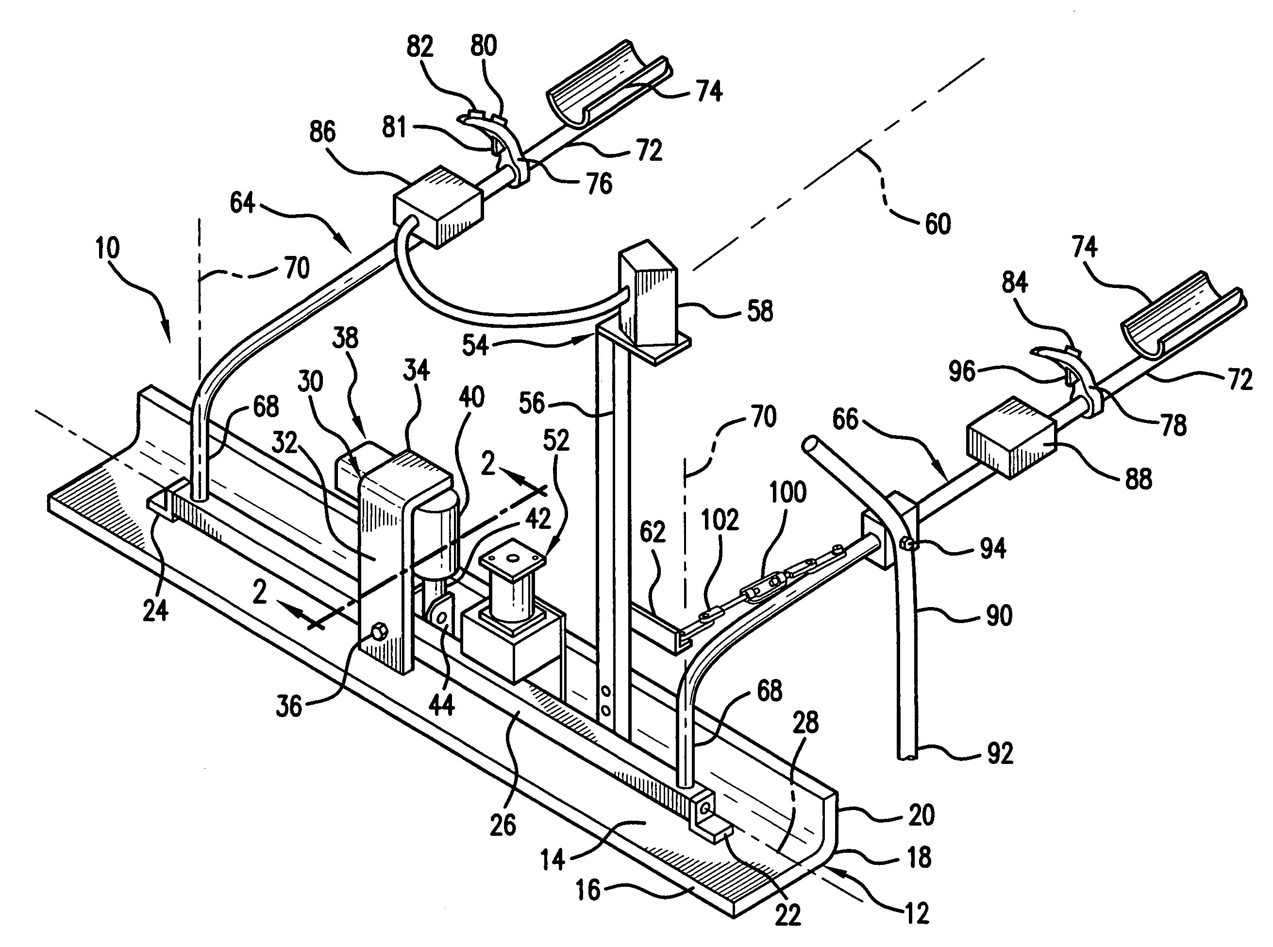
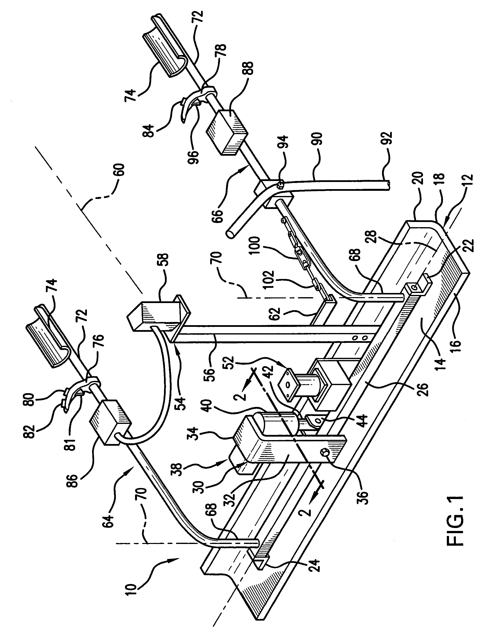
[0027]Referring to FIG. 1 a screed 10 includes a screed blade or plate 12 having a screed base 14 with a forward edge 16 and a rear edge 18. A screed flange 20 extends vertically up from the rear edge 18 so that the screed blade or plate 12 is of an L-shaped configuration. The bottom surface of the screed base 14 is adapted to rest on an uncured concrete surface.

[0028]A pair of pivot ears 22, 24 are attached to the upper surface of the screed base 14 or to screed flange 20 by welding, bolting or other securing means. The pivot ears 22, 24 are L-Shaped in configuration and include a pivot member or bar 26 pivotally mounted therebetween for pivotal movement about a horizontal pivot axis designated by the numeral 28.

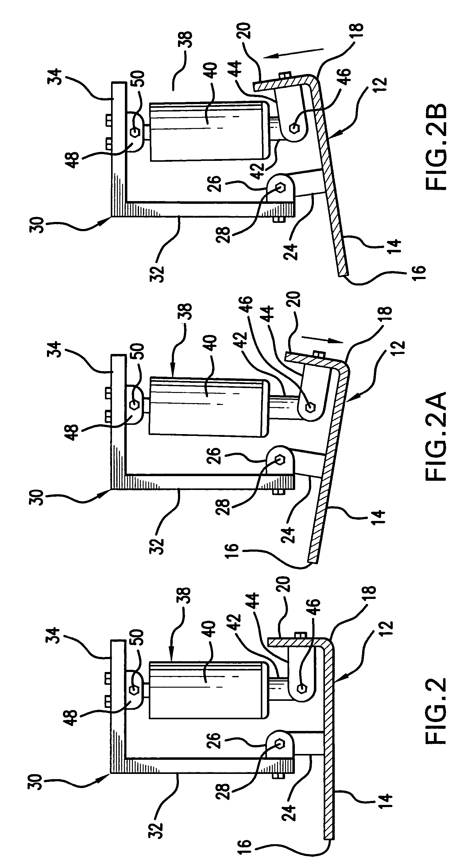
[0029]Attached to the pivot member or bar 26 by a bolt 36 and extending upwardly therefrom is a mounting bracket 30 comprising an upstanding frame member 32 and a horizontal frame member 34. Mounted to the horizontal frame member 34 is an actuator 38 which is pivotally atta...


PUM


Abstract

A screed plate includes a pair of handles mounted to a pivot member. The pivot member is connected for rotation with respect to a screed plate about a horizontal axis with respect to a screed plate. The vibrator is provided on the screed plate and a tilt actuator is connected to the pivot member and to the screed plate for causing tilting of the screed plate. A laser receiver receives a horizontal laser beam and determines whether or not the receiver is above, below, or at the same level as the laser beam. If the receiver is either above or below the laser beam it sends a signal to the tilt actuator to cause tilting of the screed plate.

Description

BACKGROUND OF THE INVENTION[0001]The present invention relates to a tilting screed and method for using same.[0002]Screeds have been used for leveling and consolidating uncured concrete. These screeds usually include a horizontal member which is moved across the surface of the concrete to level the concrete and prepare it for finishing. Vibrators are sometimes used to cause the screed to vibrate against the surface of the concrete and to consolidate it.[0003]It is desirable to be able to adjust the angle of the screed plate relative to the concrete surface. Sometimes it is desirable to lift the leading edge of the screed plate to allow more concrete under the plate for filling low areas. Other times it is desirable to lift the trailing edge of the screed plate to remove concrete from a high spot.[0004]The prior art has utilized laser receivers for receiving a horizontal laser beam. These laser receivers include a visual indication as to whether or not the screed is resting on a conc...

Claims


Application Information

Patent Timeline
IPC IPC(8): E01C19/44
CPCE01C19/402E01C19/006
Inventor SUCKOW, ROBERT E.SUCKOW, RICHARD A.
Owner SUCKOW ROBERT E
Why Eureka
Try Eureka