Eureka AIR delivers breakthrough ideas for toughest innovation challenges, trusted by R&D personnel around the world.

System and method for mitigating intermittent interruptions in an audio radio broadcast system

Inactive Publication Date: 2005-05-31
IBIQUITY DIGITAL CORP
View PDF11 Cites 65 Cited by
  • Summary
  • Abstract
  • Description
  • Claims
  • Application Information

AI Technical Summary

Benefits of technology

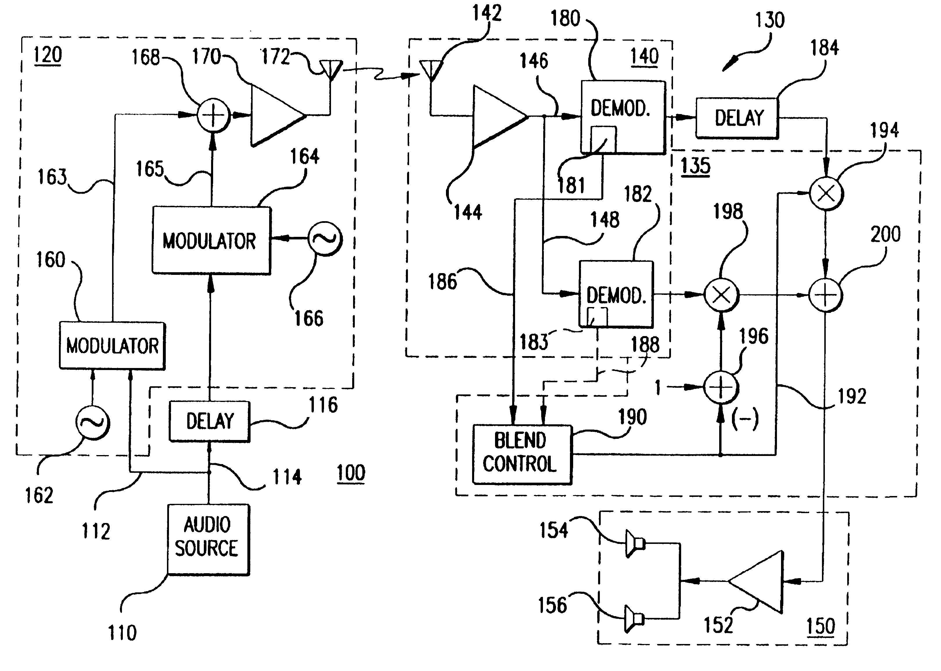
[0007]A system for mitigating intermittent interruptions in an audio radio broadcast system is provided. The system includes a source of an audio signal-and a transmitter subsystem having a first input coupled to the audio source for modulating at least one first carrier signal with the audio signal to broadcast a primary radio signal. The system also includes a first delay circuit having an input coupled to the audio source for adding a first predetermined time delay to the audio signal to form a delayed redundant audio signal at an output thereof, the output being coupled to a second input of the transmitter subsystem for modulating at least one second carrier signal with the delayed redundant audio signal to broadcast a delayed redundant radio signal simultaneously with the primary radio signal. The system further includes a receiver subsystem for receiving the primary radio signal and the delayed redundant radio signal, the receiver subsystem demodulating the primary radio signal to provide the audio signal to a first output thereof and demodulating the delayed redundant radio signal to provide the delayed redundant audio signal to a second output thereof. The receiver subsystem includes a circuit for detecting degradation of the received primary radio signal, the circuit for degradation detection providing a quality measurement signal to a third output of the receiver subsystem. The system includes a second delay circuit having an input coupled to the first output of the receiver subsystem for adding a second predetermined time delay to the audio signal to form a delayed primary audio signal at an output thereof, the second predetermined time delay being substantially equal to the first predetermined time delay. Still further, the system includes a blending circuit having a first input coupled to an output of the second delay circuit and second and third inputs respectively coupled to the second and third outputs of the receiver subsystem for combining a first weighting factor with the delayed primary audio signal and a second weighting factor with the delayed redundant audio signal and combining the weighted delayed primary audio signal with the weighted delayed redundant audio signal to form a composite audio signal. The first weighting factor is smoothly transitioned between a first value and a second value responsive to the quality measurement signal being less than a predetermined threshold value. The second weighting factor is smoothly transitioned between the second value and the first value responsive to the quality measurement signal being less than the predetermined threshold value. Additionally, the system includes an audio output circuit coupled to the blending circuit for converting the composite audio signal to an aural signal.

Problems solved by technology

In automotive applications, however, fading and blockage statistics are not stationary, being dependent on the vehicle location and velocity, and effective mitigation requires more sophisticated methods.
Terrestrial DAB systems generally have the characteristic that fades and blockages have a more deleterious effect on received audio than they do on analog modulated systems, such as commercial AM or FM broadcasts because these DAB systems do not degrade gracefully.
Therefore, the IBOC DAB concept allows a station to offer digital audio while retaining its analog listeners, but the digital broadcast will not gain acceptance unless the audio loss due to temporary fades and blockages is mitigated.

Method used


Image

  • System and method for mitigating intermittent interruptions in an audio radio broadcast system
  • System and method for mitigating intermittent interruptions in an audio radio broadcast system
  • System and method for mitigating intermittent interruptions in an audio radio broadcast system

Examples


Embodiment Construction

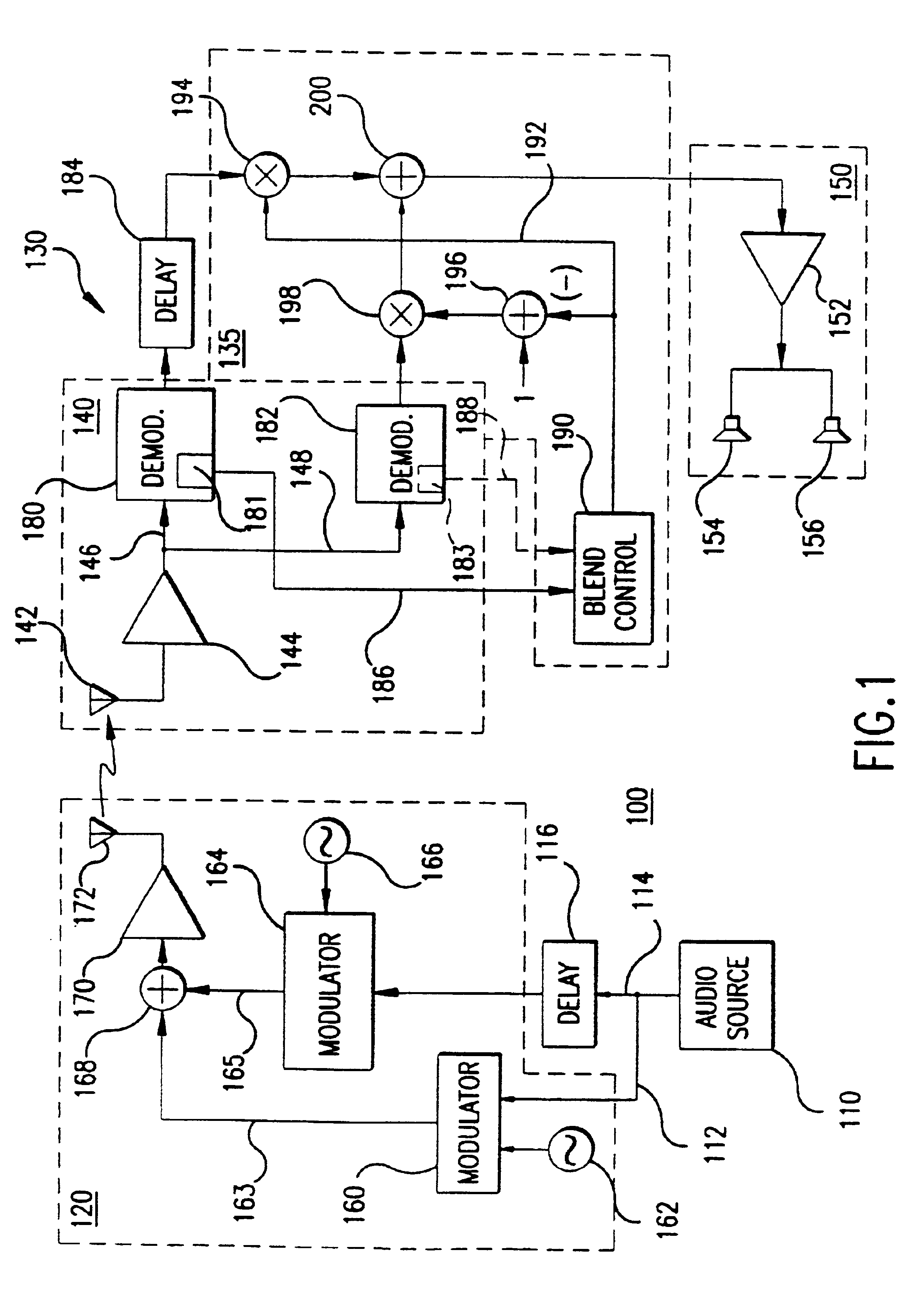
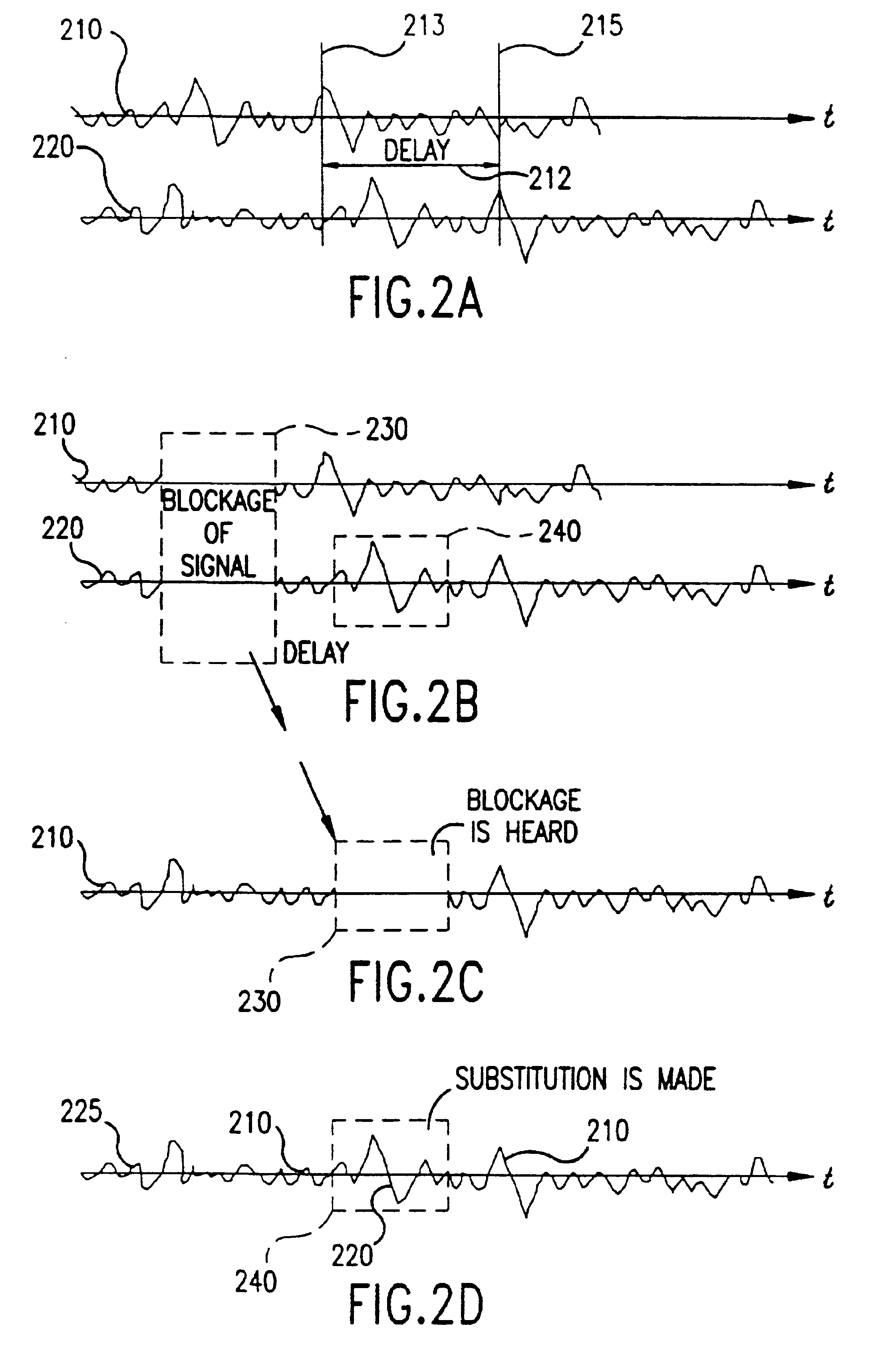
[0023]Referring to FIGS. 1-9, and particularly to FIG. 1, there is shown system 100 for mitigating intermittent interruptions in an audio radio broadcast system. Conventionally, FM radios mitigate the effects of fades or partial blockages by transitioning from full stereophonic audio to monophonic audio. Some degree of mitigation is achieved because the stereo information which is modulated on a subcarrier, requires a higher signal-to-noise ratio to demodulate to a given quality level than does the monophonic information which is at the base band. However, there are some blockages which sufficiently “take out” the base band and thereby produce a gap in the reception of the audio signal. System 100 is designed to mitigate even those latter type outages in conventional analog broadcast systems and particularly adapted for use in digital audio broadcast (DAB) systems, where such outages are of an intermittent variety and do not last for more than a few seconds. To accomplish that mitig...


PUM


Abstract

A system is provided wherein a primary radio signal and a redundant radio signal are transmitted from a transmitter subsystem and received by a receiver subsystem. The output of an audio source is coupled to a modulator for modulating a radio frequency signal for coupling to a transmit antenna. A second output of audio source is coupled to a delay circuit, for adding a predetermined time delay thereto. The delayed audio source signal is coupled to a modulator for modulating a second radio frequency signal that is also coupled to the transmit antenna. The receiver subsystem receives both the primary radio signal and the delayed redundant radio signal and couples each to a respective demodulator. At least one demodulator includes a circuit for determining the degradation in the primary radio signal and provides a quality measurement output signal to a blend control circuit.

Description

CROSS REFERENCE TO RELATED APPLICATION[0001]This application is a divisional application of U.S. patent application Ser. No. 08 / 947,902, filed Oct. 9, 1997, now U.S. Pat. No. 6,178,317.BACKGROUND OF THE INVENTION[0002]1. Field of the Invention[0003]This invention directs itself to a system and method of mitigating the effects of signal fades, temporary blockages or severe channel impairments in an audio broadcasting system. More particularly, the system and method employs the transmission of a primary broadcast signal along with a redundant signal, the redundant signal being delayed by a predetermined amount of time, on the order of several seconds, with respect to the primary broadcast signal. A corresponding delay is incorporated in the receiver for delaying the received primary broadcast signal. Still further, this invention is directed to the concept of detecting degradation in the primary broadcast channel that represents a fade or blockage in the RF signal, before such is perc...

Claims


Application Information

Patent Timeline
IPC IPC(8): H04H1/00H04L27/26H04B7/12H04B7/02H04L1/02H04L27/00H04B1/16H04H20/46H04L1/04H04L27/32
CPCH04B7/12H04H20/22H04L1/02H04H60/11H04H20/30H04L5/0005H04H2201/183H04H2201/20
Inventor KROEGER, BRIAN W.STEHLIK, ROY R.
Owner IBIQUITY DIGITAL CORP
Why Eureka
Eureka Blog
Learn More