Knee protecting airbag device

an airbag device and knee technology, applied in the direction of pedestrian/occupant safety arrangement, vehicle components, superstructure subunits, etc., can solve the problems of inadequate appearance and design, inadequate contact between the expansion and inflated airbag and the advancing knee of the occupant, and the inability to present adequate appearance and design, etc., to achieve the effect of smooth completion of the inflation

Inactive Publication Date: 2005-06-07
TOYODA GOSEI CO LTD
View PDF18 Cites 30 Cited by
  • Summary
  • Abstract
  • Description
  • Claims
  • Application Information

AI Technical Summary

Benefits of technology

[0056]With this construction, the cap is arranged at a position which is covered with the airbag having completed its expansion and inflation, but the connection means is arranged on the door side of the cap peripheral edge. Therefore, even if the retaining pawls come out of the mounting hole peripheral edge and are far from the general portion of the airbag cover, the door side of the cap peripheral edge does not come off and far from the general portion of the airbag cover by the connection means. While the airbag is being expanded and inflated, the retaining pawls of the cap are hidden by the body of the cap so that the airbag completes its inflation smoothly without any hindrance by the retaining pawls.

Problems solved by technology

When the case is fixed to a predetermined position of the vehicle, however, there may arise an assembling error such as dimensional inconsistency between the airbag cover and the interior members.
In this case, an adequate appearance and design cannot be presented because of steps or gaps between the airbag cover and the interior members.
At this time, the following problem may arise if the distance between the upward-opening door and an occupant, before opening, is different at one of the left and right side edge and at the other because of the circumferential design.
As a result, the expanded and inflated airbag does not contact the advancing knee of the occupant properly.

Method used


Image

  • Knee protecting airbag device
  • Knee protecting airbag device
  • Knee protecting airbag device

Examples


first embodiment

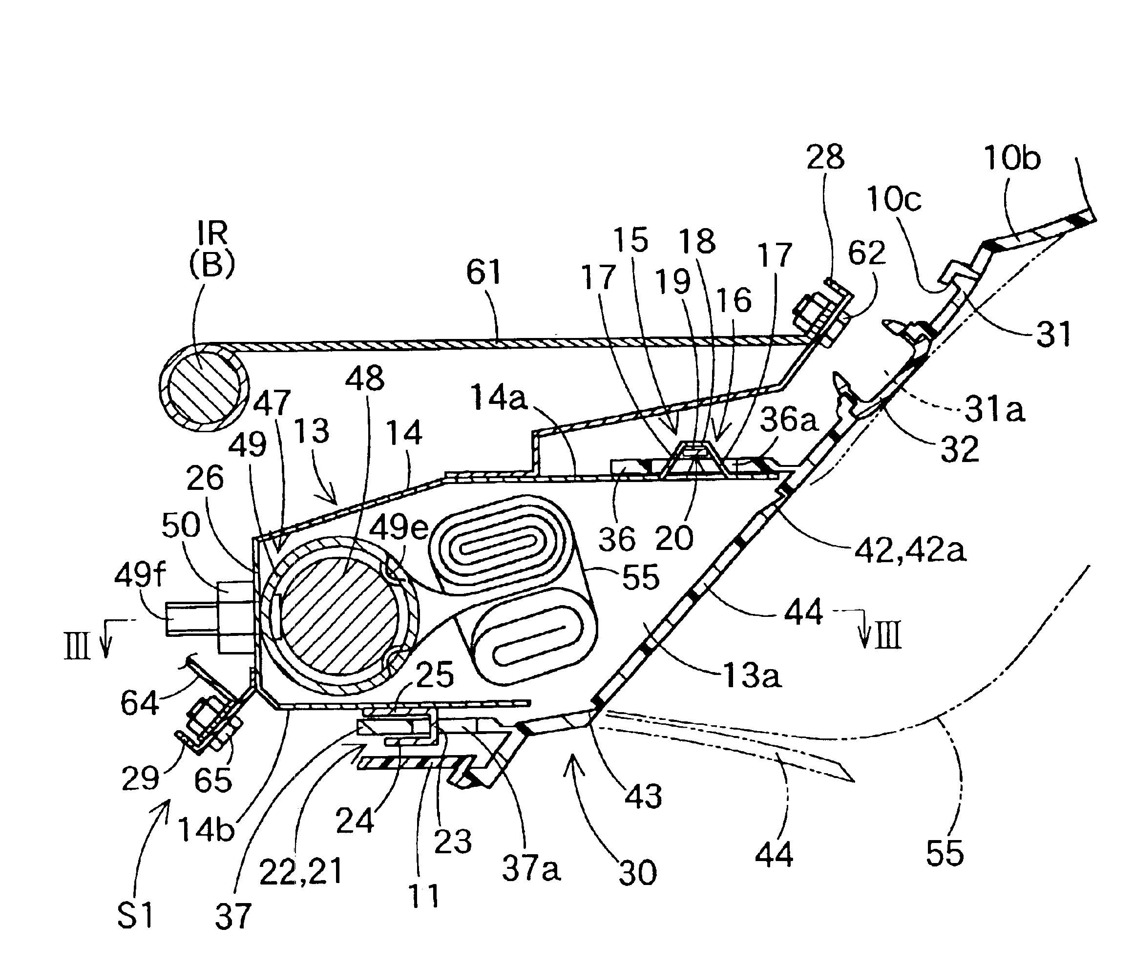
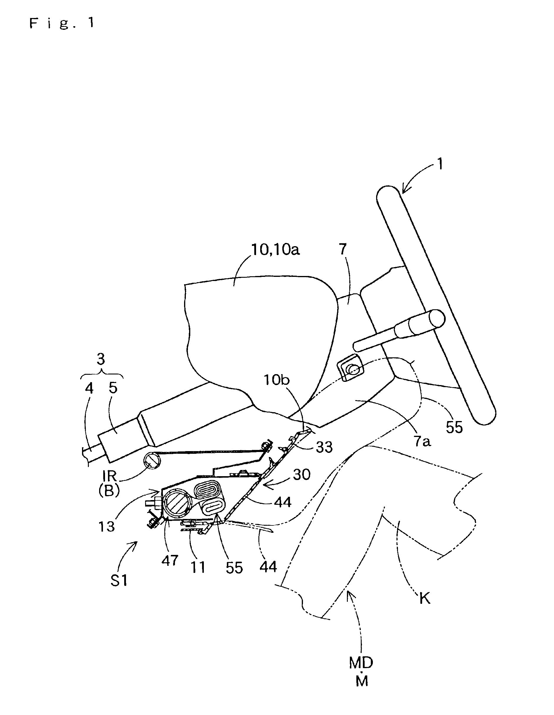
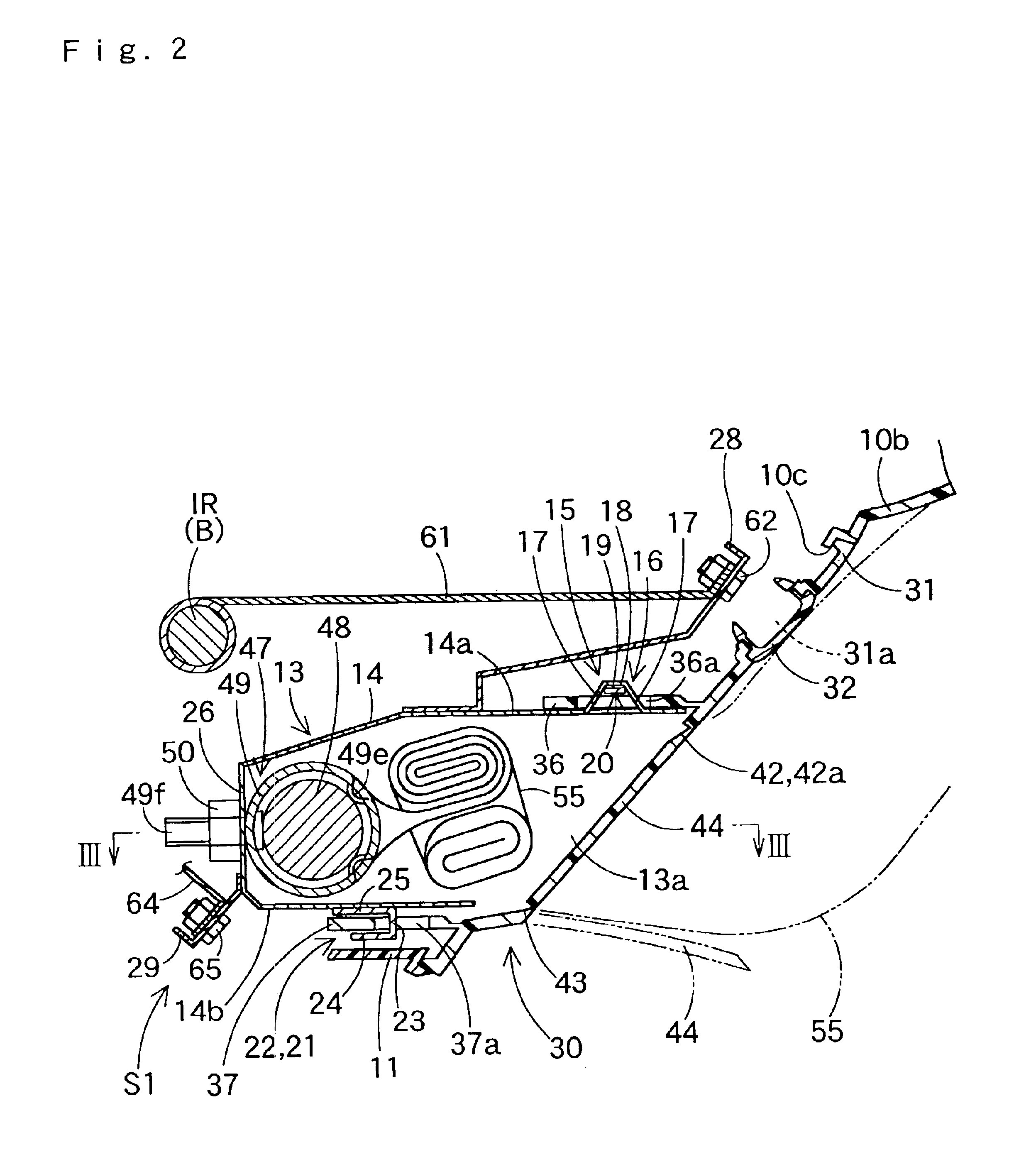
[0085]As shown in FIGS. 1 to 3, a knee protecting airbag device S1 is so arranged under a steering column 3 on the vehicular front side of a driver MD or an occupant M as to protect the knees K (KL and KR) of the driver MD.

[0086]Here, the vertical, transverse and longitudinal directions in this Specification correspond to the vertical, transverse and longitudinal directions of the vehicle at the time when the knee protecting airbag device S1 is mounted on the vehicle.

[0087]The steering column 3 is constructed, as shown in FIG. 1, to include a main shaft 4 connected to a steering wheel 1, and a column tube 5 covering the main shaft 4. Between the main shaft 4 and the column tube 5, there are arranged a not-shown tilt mechanism to adjust the angle of the ring face of the steering wheel 1, a not-shown telescopic mechanism to move and stop the steering wheel 1 in the axial direction of the shaft 4, and so on.

[0088]A column cover 7 is formed of a synthetic resin into a generally square ...

second embodiment

[0122]In the airbag device S2 of the second embodiment, too, the upper wall portion (or the assembling piece) 36 has a thickness t4 set smaller than the length L5 of the retaining frame 73 in the assembling body 72, and the assembling hole 36a has a longitudinal length w7 set larger than the thickness t5 of the retaining frame 73, as shown in FIG. 11. The assembling hole 36a has a transverse width w8 set wider than the transverse width w9 of the assembling body 72 (or the retaining frame 73), as shown in FIG. 10. By these settings, in other words, with the bent portions 74 of the assembling bodies 72 being retained on the peripheral edges of the assembling holes 36a, the upper wall portion 36 is so retained on the case 69 as is movable vertically, longitudinally and transversely. Here, the bent portions 74 have a length L6 set so shorter than the longitudinal length w7 of the assembling holes 36a as can be inserted into the assembling holes 36a.

[0123]The case 69 thus constructed co...

third embodiment

[0141]In the case of the third embodiment, moreover, in the vertical lines 147 and 148 of the H-shaped breakage-expected portion 146, the upper ends 147a and 148a and the lower ends 147b and 148b are positioned at the same level, respectively. In the downward operable door 153, therefore, the lefthand side edge 153b closer to the driver MD is given a longer length, and the other righthand side edge 153c apart from the driver MD is given a shorter length. Here, FIG. 16 shows, by the double-dotted lines, the doors 151 and 153 slightly returning toward the horizontal direction after they are fully opened in the vertical direction.

[0142]In the general portion 138 of the airbag cover 137 and at predetermined positions near the outer peripheral edge, there are formed a plurality of retaining legs 139, which are formed to extend toward the vehicular front side for a connection with the lower panel 10b, as shown in FIG. 14. These retaining legs 139 are retained on the peripheral edges of th...


PUM


Abstract

A knee protecting airbag device comprises an airbag, an inflator, a case and an airbag cover to be assembled with the case. The case houses the airbag and the inflator, and is fixed to the side of the vehicular body with its rear side open. The airbag cover includes a door and a general portion around the door. The door closes the opening of the case and opens when the airbag expands and inflates. The general portion is surrounded by interior members of the vehicle when mounted on the vehicle. The knee protecting airbag device is mounted on the vehicle in an assembled state in which the airbag, the inflator and the airbag cover are joined to the case. The airbag cover is joined to the case in a movable manner so as to absorb the dimensional inconsistency between itself and the surrounding interior members.

Description

[0001]The present application claims priority to Japanese patent application of Suzuki et al., filed Jan. 11, 2002, No. 2002-005179, Japanese patent application of Suzuki et al., filed Jan. 11, 2002, No. 2002-005192, and Japanese patent application of Takimoto, filed Jun. 11, 2002, No. 2002-169876, the entirety of each is hereby incorporated into the present application by this reference.BACKGROUND OF THE INVENTION[0002]1. Field of the Invention[0003]The present invention relates to a knee protecting airbag device in which an airbag to be expanded and inflated with an inflating gas let in protects the knee of an occupant such as a driver and a front seat passenger.[0004]2. Description of Related Art[0005]As disclosed in Japanese Patent Laid-Open No. Hei 10-315894, the device for protecting the knee of an occupant in the prior art has a case, which houses a folded airbag and an inflator for feeding the airbag with inflation gas, at the lower side of the column cover below the steerin...

Claims


Application Information

Patent Timeline
Patent Type & Authority Patents(United States)
IPC IPC(8): B60R21/20B60R21/16B60R13/02B60R21/205B60R21/2165B60R21/217B60R21/231
CPCB60R21/206B60R21/2171B60R21/2165B60R13/0256B60R13/0275B60R2021/23169B60R2021/2172
Inventor SUZUKI, KAZUMASATAKIMOTO, MASAHIROMIZUNO, YOSHIONAGATA, ATSUSHIKAGOHASHI, RYOJI
Owner TOYODA GOSEI CO LTD
Why Eureka
Try Eureka