Method and system for ensuring that a train operator remains alert during operation of the train

a technology for operators and trains, applied in the field of wayside signaling, can solve problems such as unsuitable for some applications, installation of expensive wayside equipment, and the need for signal recognition

Inactive Publication Date: 2005-06-07
SIEMENS MOBILITY INC
View PDF52 Cites 113 Cited by
  • Summary
  • Abstract
  • Description
  • Claims
  • Application Information

AI Technical Summary

Problems solved by technology

However, train operators are human and can sometimes miss a signal, which can result in disaster.
A number of systems have been designed to address this problem, but each of these systems has drawbacks that make them unsuitable for some applications.
However, this system has several drawbacks.
First, it requires the installation of expensive wayside equipment to transmit the signal to the locomotive cab through the rails.
Second, the system only requires acknowledgment of signals.
Simply requiring acknowledgment of signals does not ensure that an operator is alert.
It is known to those of skill in the art that operators can successfully acknowledge signals while in only a semi-conscious state referred to as “micro-sleep.” Although some embodiments of the cab signal system will stop the train if a signal is not obeyed, this after-the-fact response may not be sufficient to prevent an accident.
This is disadvantageous because if an operator misses a less restrictive signal, the operator may miss an opportunity to operate the train more efficiently by increasing the speed of the train.
Although the radio frequency communication equipment used in such systems is less expensive than the equipment used in the cab signal systems, it still increases costs, especially in a railroad in which a wayside signaling system is already in place.
While this system is advantageous in that it does not require any equipment to transmit signals to trains in the system in addition to a wayside signaling system, it has the drawback of requiring two crew members.

Method used


Image

  • Method and system for ensuring that a train operator remains alert during operation of the train
  • Method and system for ensuring that a train operator remains alert during operation of the train
  • Method and system for ensuring that a train operator remains alert during operation of the train

Examples


Embodiment Construction

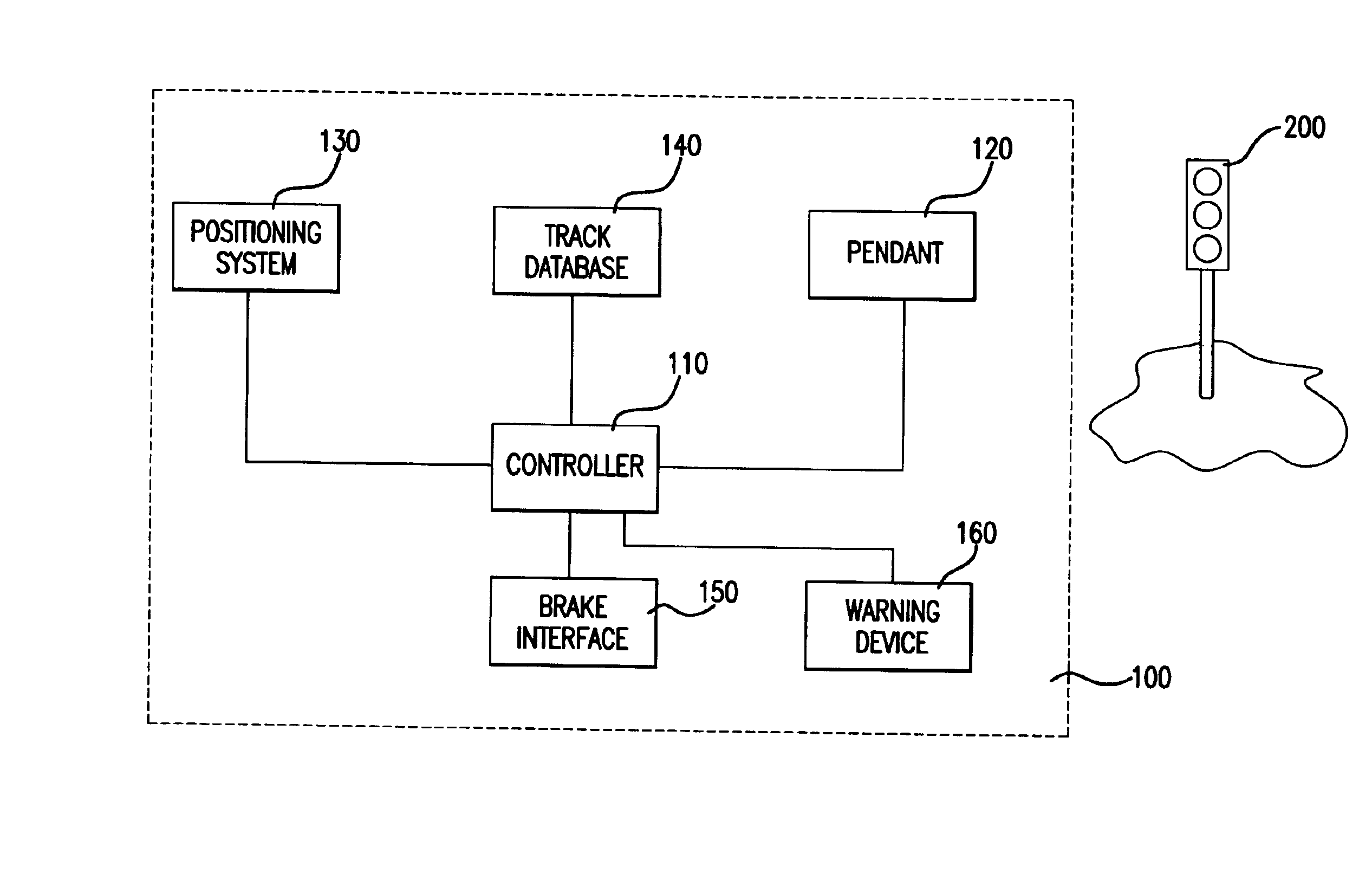
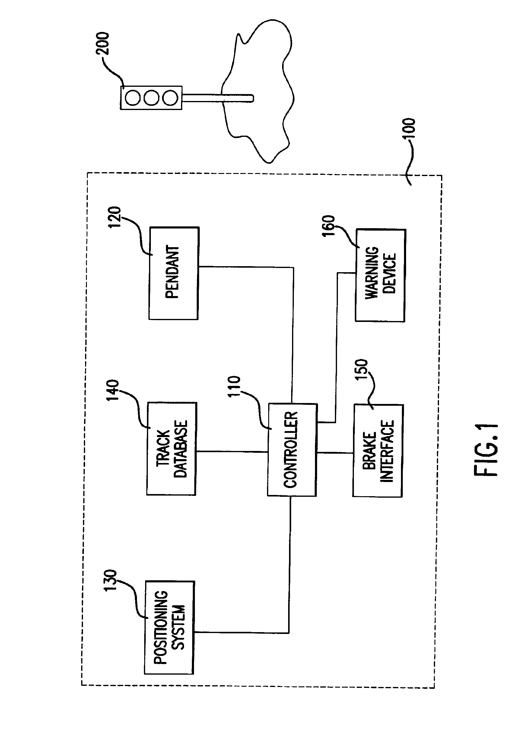
[0022]The present invention will be discussed with reference to preferred embodiments of train control systems. Specific details, such as types of signals, are set forth in order to provide a thorough understanding of the present invention. The preferred embodiments discussed herein should not be understood to limit the invention. Furthermore, for ease of understanding, certain method steps are delineated as separate steps; however, these steps should not be construed as necessarily distinct nor order dependent in their performance.

[0023]A train control system 100 is illustrated in FIG. 1. The system 100 includes a controller 110. The controller 110 may be a microprocessor or may be implemented using discrete components. The controller 110 is responsible for implementing the logical operations discussed in detail below.

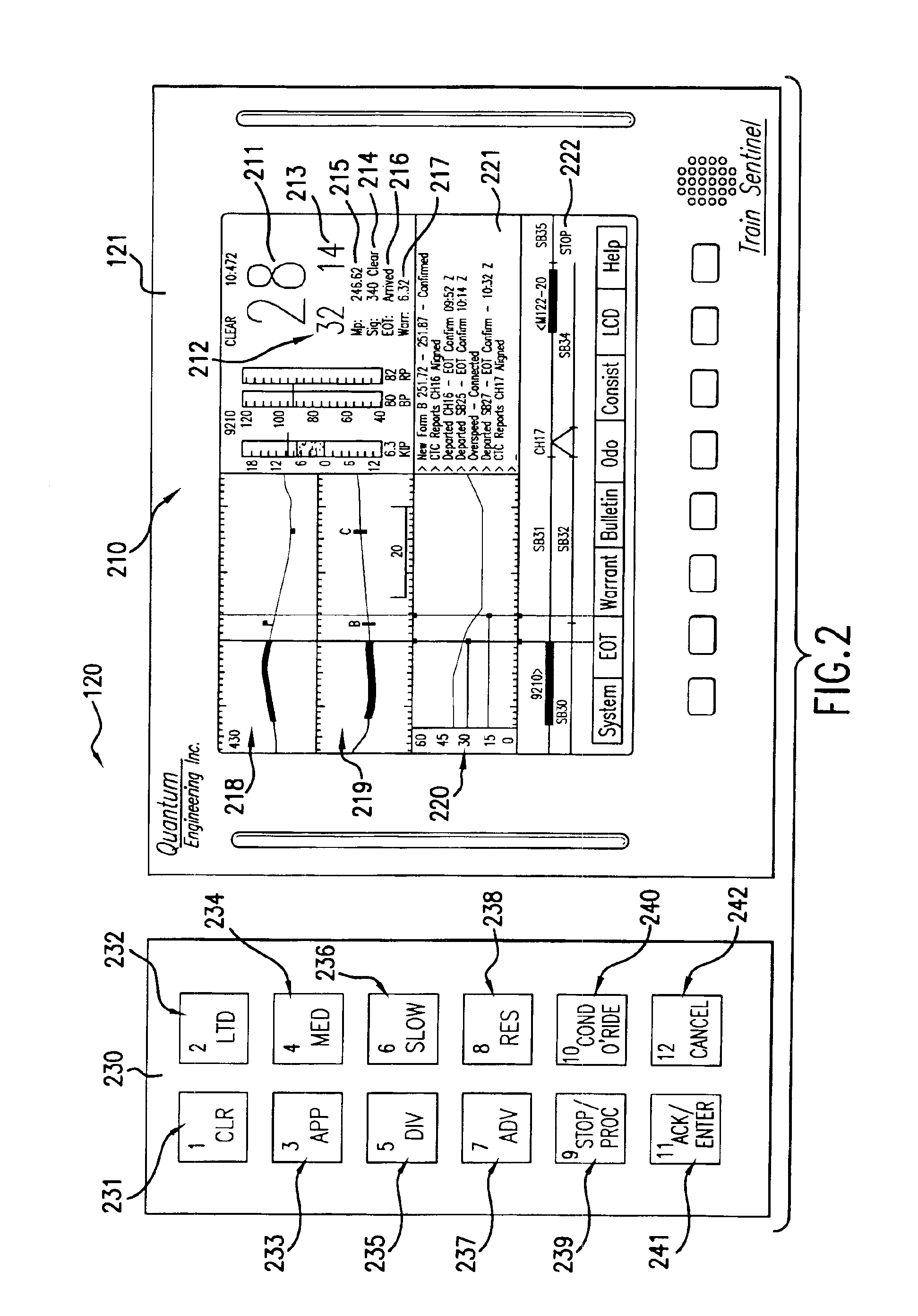
[0024]An operator pendant 120 is connected to the controller 110. The operator pendant 120 is illustrated in further detail in FIG. 2. The operator pendant 120 includ...


PUM


Abstract

A train control system requires a train operator to enter signal aspect information at each wayside signal position on a railroad and stops the train if the operator fails to enter aspect information without communicating with the wayside signal device to verify that the information entered by the operator is correct, In some embodiments, the signal aspect information is entered by pressing a button corresponding to the signal aspect information, and the location and / or arrangement of the buttons changes. Alternatively, the operator must repeat a varying sequence (such as a series of button pushes) in conjunction with and / or in addition to entering signal aspect information.

Description

BACKGROUND OF THE INVENTION[0001]1. Field of the Invention[0002]The invention relates to wayside signaling generally and more particularly to wayside signal acknowledgment systems.[0003]2. Discussion of the Background[0004]Trains are often controlled by wayside signaling systems. A wide variety of wayside signal systems are known in the art. In traditional wayside signaling systems (e.g., Automated Block signaling (ABS) and Centralized Track Control (CTC) systems), one or more colored signal lights mounted on poles alongside a track are used to direct a train operator as to how to move the train. These wayside signals may be located at various positions on the railway such as near the beginning of a block of track and near grade crossings, sidings, switches, etc.[0005]The signal lights indicate whether and under what conditions (e.g., what speed) a train is to proceed in a section of track associated with the signal. The meaning of the wayside signal is sometimes referred to as the ...

Claims


Application Information

Patent Timeline
Patent Type & Authority Patents(United States)
IPC IPC(8): B61L15/00G08B21/00G08B21/06
CPCB61L15/009B61L25/021G08B21/06B61L25/026B61L25/025B61L2205/04
Inventor KANE, MARK EDWARDSHOCKLEY, JAMES FRANCISHICKENLOOPER, HARRISON THOMAS
Owner SIEMENS MOBILITY INC
Why Eureka
Try Eureka