

Display
- Summary
- Abstract
- Description
- Claims
- Application Information
AI Technical Summary
Benefits of technology
Problems solved by technology
Method used
Image


Examples
Embodiment Construction
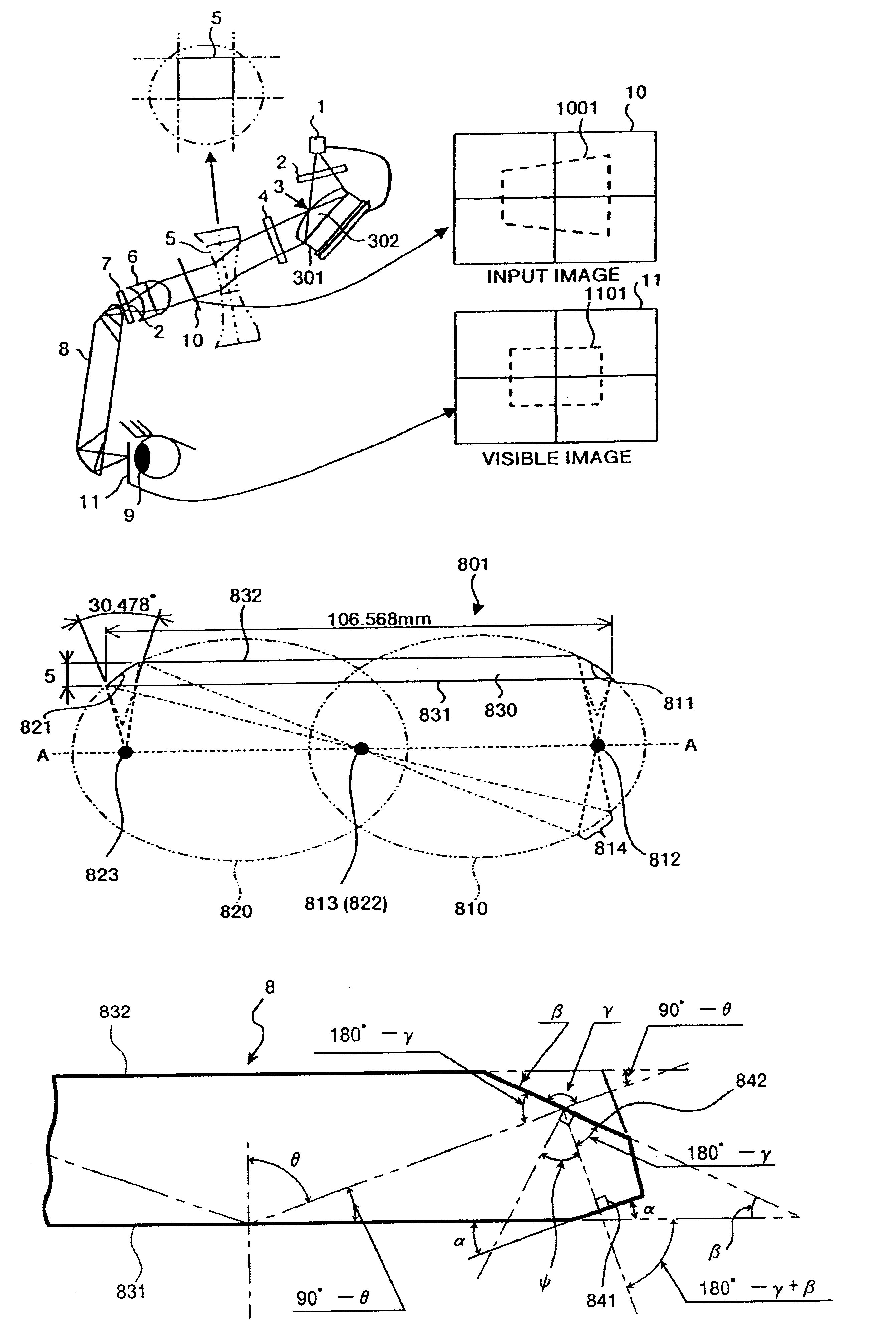
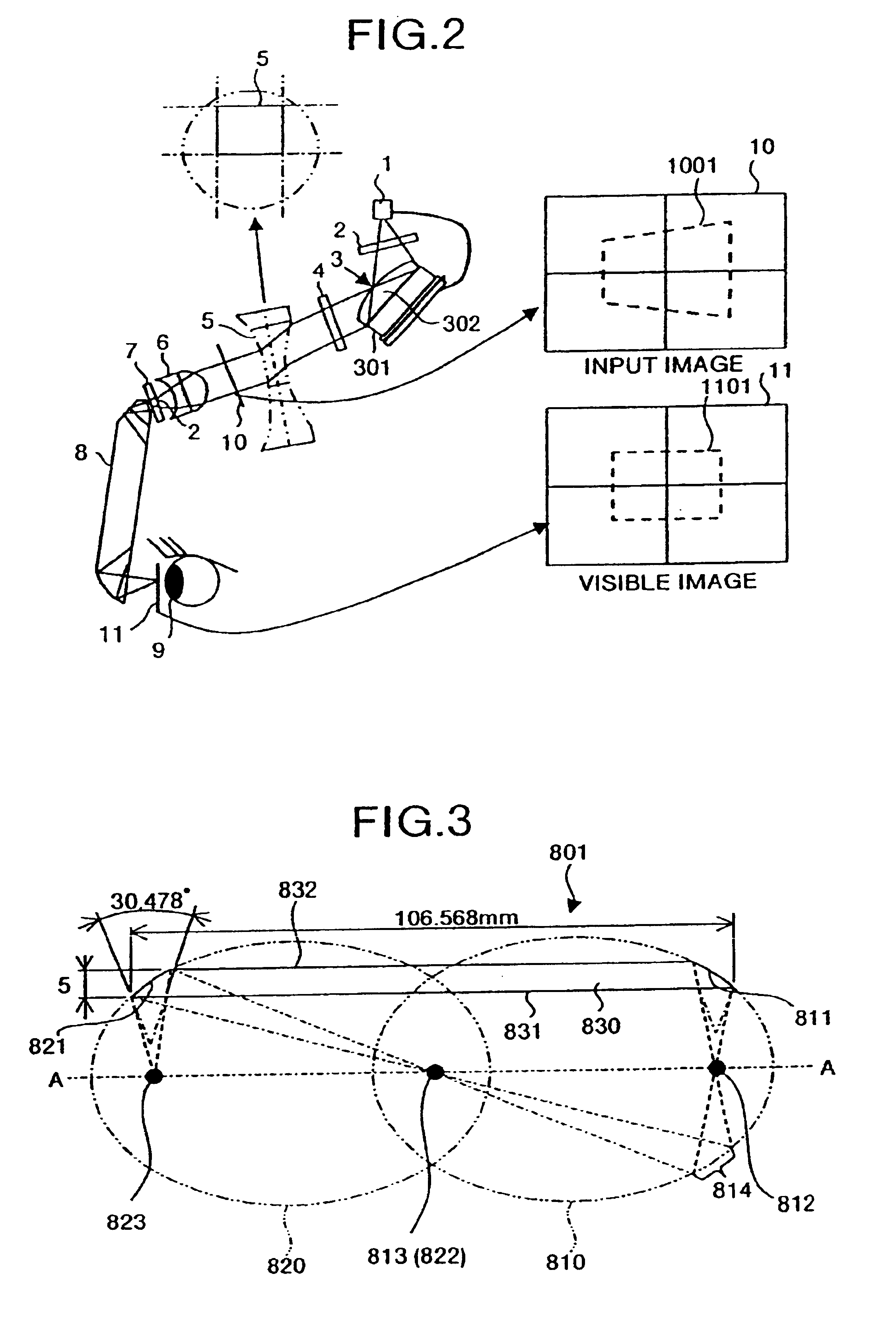
[0027]The embodiments of the present invention will be explained below, with reference to the drawings. FIG. 2 is a diagram which shows one example of an optical system of a display according to the present invention. As shown in FIG. 2, this optical system comprises, a light emission element 1 consisting of for example a light emitting diode (LED), a polarizer 2 consisting of a polarizing plate, a display device 3 comprising a liquid crystal display device unit 301 and a field lens 302 integrated therewith, an analyzer 4 consisting of a polarizing plate, a correcting lens 5, an imaging device 6 consisting of an imaging lens, a pinhole element 7 with a pinhole 701 being open, and a divided light-guiding body 8.
[0028]In this optical system, light emitted from the light emission element 1 goes through the polarizer 2 to shine into the field lens 302, and is reflected on the reflection type liquid crystal display device of the liquid crystal display device unit 301. The reflected light...
PUM
 Abstract
Description
Claims
Application Information