Tool-less wall-mount distributed filter housing

a filter housing and toolless technology, applied in the field of wall-mount housings, can solve the problems of service delays, substantial expense, and the installer cannot provide adequate viewing of the housing alignment during the installation process

a filter housing and toolless technology, applied in the field of wall-mount housings, can solve the problems of service delays, substantial expense, and the installer cannot provide adequate viewing of the housing alignment during the installation process

US6904149B2Inactive Publication Date: 2005-06-07CORNING OPTICAL COMM LLC

Image

  • Tool-less wall-mount distributed filter housing
  • Tool-less wall-mount distributed filter housing
  • Tool-less wall-mount distributed filter housing

Examples


Embodiment Construction

[0026]One or more embodiments of the invention will be described hereinafter in sufficient detail to permit one of ordinary skill in the art to make, use and practice the invention without undue experimentation. The embodiments shown and described herein are exemplary only and are not intended to limit the scope of the invention, as defined by the appended claims, in any manner. Instead, the invention is intended to be construed broadly with reference to this detailed description and the accompanying drawings, in which like reference numerals indicate like parts in the various views.

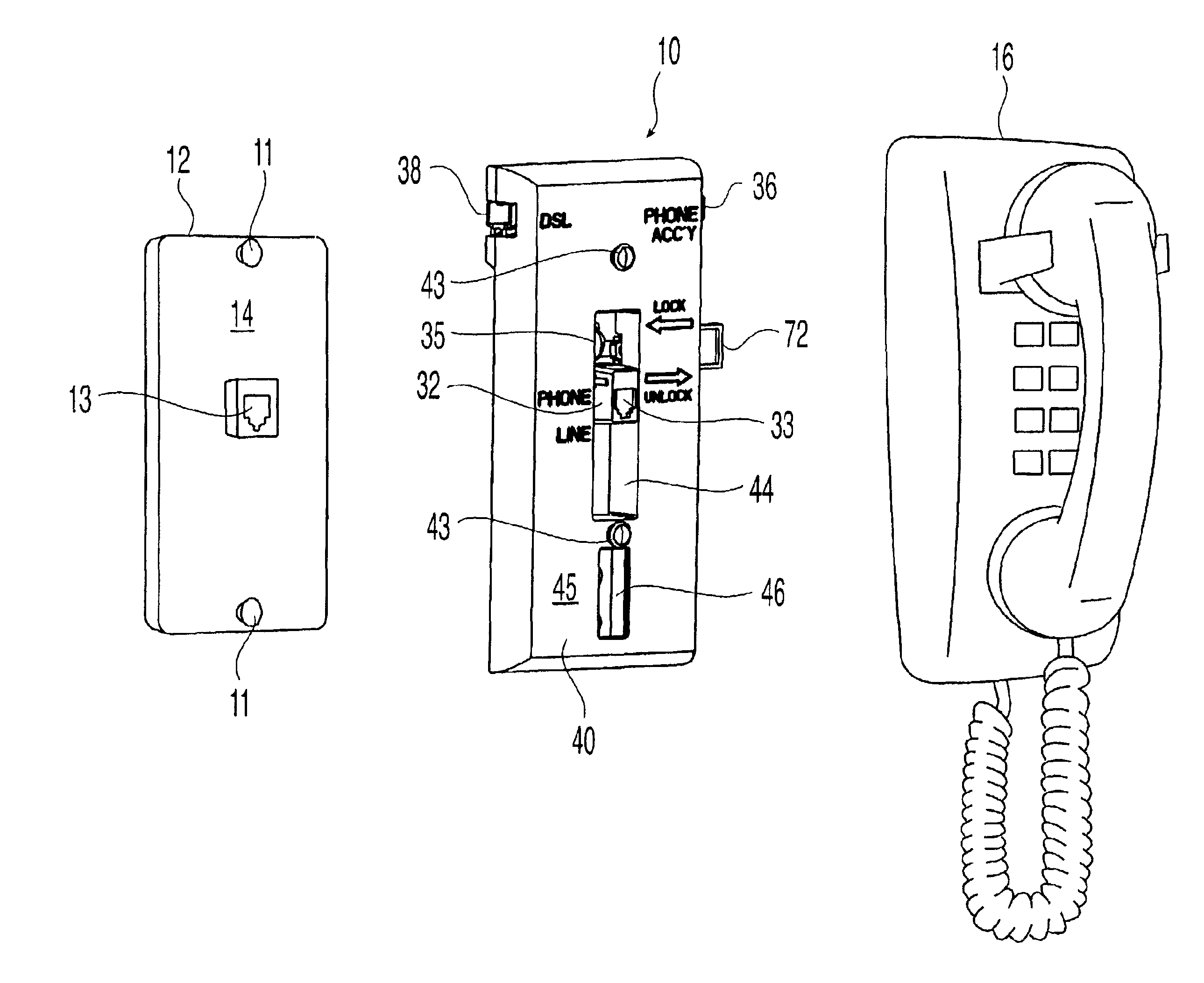
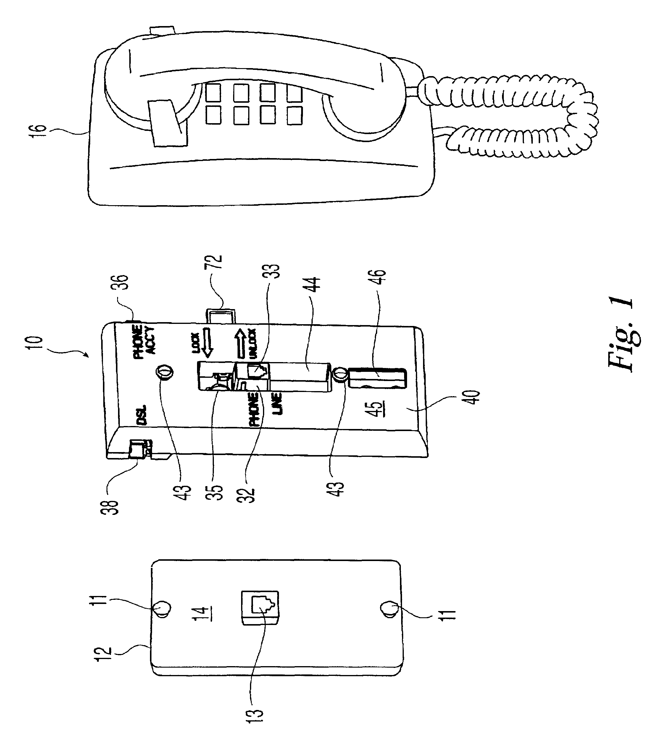
[0027]FIG. 1 illustrates a housing 10 for a distributed filter constructed in accordance with the present invention removably mounted to a wall plate 12 between the wall plate 12 and a conventional wall-mount telephone 16. The wall plate 12 comprises a pair of mounting studs 11 and a phone jack 13 centrally disposed on the wall plate 12 between the mounting studs 11. The phone jack 13 is commonly referre...


PUM


Abstract

A housing for a distributed filter removably mounts to a wall plate between the wall plate and a wall-mount telephone without the use of a tool. The housing includes a base and a cover attached to the base that together define a cavity. A filter circuit for filtering voice signals is disposed within the cavity. A phone jack and at least one auxiliary jack are also disposed in the cavity and accessible through the cover. In one embodiment, viewing windows are formed through the cover to permit an installer to view the mounting studs on the wall plate during installation. A slide lock is also provided to secure the housing to the wall plate. In another embodiment, a push-button lock is provided to secure the housing to the wall plate. The push-button is forced outwardly during installation when a mounting stud engages a slot formed in the base and is subsequently depressed to secure the housing to the wall plate.

Description

CROSS REFERENCE TO RELATED APPLICATIONS[0001]This application is a continuation-in-part of U.S. Design application Ser. No. 29 / 127,805, filed Aug. 11, 2000. This application claims the benefit of U.S. Provisional Application No. 60 / 224,705, filed Aug. 11, 2000.FIELD OF THE INVENTION[0002]The invention relates generally to a wall-mount housing for use at subscriber premises. More particularly, the invention is a wall-mount housing for a distributed filter to separate voice and data signals at a subscriber premises that does not require tools for installation.BACKGROUND OF THE INVENTION[0003]High speed Internet access is becoming increasingly commonplace in commercial and residential telecommunications installations. One technology being used for high speed Internet access is commonly known as splitter-less asymmetrical digital subscriber line (“Splitter-Less ADSL”) or “G.Lite.” However, several other forms of digital subscriber line (“DSL”) services exist, collectively referred to as...

Claims


Application Information

Patent Timeline
07 Jun 2005
Publication
US6904149B2
IPC
H04M1/02
CPC
H04M1/0297; H04M1/0293
Inventors
KEENUM, JOHN A.; MENKE, BRETT A.