Distributed filtering method for fault diagnosis in a sensor network

a sensor network and filtering technology, applied in the field of fault diagnosis mechanisms in sensor networks, can solve the problems of large distance between sensor nodes, use of such techniques, and ever increasing complexity of modern engineering systems, and achieve the effect of increasing the reliability of the fault detection mechanism

Inactive Publication Date: 2018-04-03
KING FAHD UNIVERSITY OF PETROLEUM AND MINERALS
View PDF2 Cites 7 Cited by
  • Summary
  • Abstract
  • Description
  • Claims
  • Application Information

AI Technical Summary

Benefits of technology

[0009]According to one embodiment, the Kalman filer residual is an indicator of a fault in both the subsystems and sensors located in the path between the pair of the KF's inputs used. Bayes decision strategy is further used to assert the presence or absence of a fault. The subsystems and sensors located in the path between the pair of inputs driving the KFs whose residuals are used to assert the presence of a fault, are assigned ‘binary 1's’ while the subsystems and sensors located in other paths are assigned ‘binary 0's’. Thus the physical system formed of all subsystems and sensors used is transformed into an equivalent binary tree that is governed by a truth table from which tree branches containing faulty subsystems and sensors are identified and the faulty elements, both detected and isolated using binary logic. Further, according to another embodiment, multiple faults in either sensors or subsystems are successfully isolated as long as both sensor and subsystem faults do not occur simultaneously. A fault in a subsystem or in a sensor is cross-checked by analyzing different paths between sensor nodes, thereby increasing the reliability of the fault detection mechanism.

Problems solved by technology

Modern engineering systems are ever increasing in complexity and tend to be distributed over wide areas, thus relying on a network of sensors to collect the necessary data.
A critical limitation in the widespread use of such techniques to detect (and isolate faults) is the large distance between the sensor nodes.
For instance, the case wherein, the distance between two sensor nodes in a network is large, and a Kalman filter is activated with all the inputs of the network, may possibly lead to a faulty detection.
Furthermore, activating each KF with all the inputs, poses memory limitations and speed limitations on a processor that performs computations to determine the location of faults within the network.

Method used


Image

  • Distributed filtering method for fault diagnosis in a sensor network
  • Distributed filtering method for fault diagnosis in a sensor network
  • Distributed filtering method for fault diagnosis in a sensor network

Examples


Embodiment Construction

[0025]Kalman filtering (also referred to herein as linear quadratic estimation (LQE) technique), uses a series of measurements observed over time, containing noise (random variations) and other inaccuracies, and produces estimates of unknown variables that tend to be more precise than those based on a single measurement alone. More formally, a Kalman filter operates recursively on streams of noisy input data to produce a statistically-optimal estimate of the underlying system state.

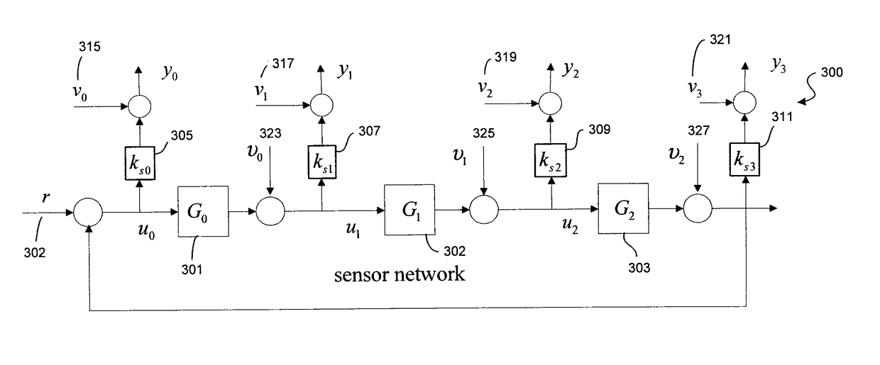
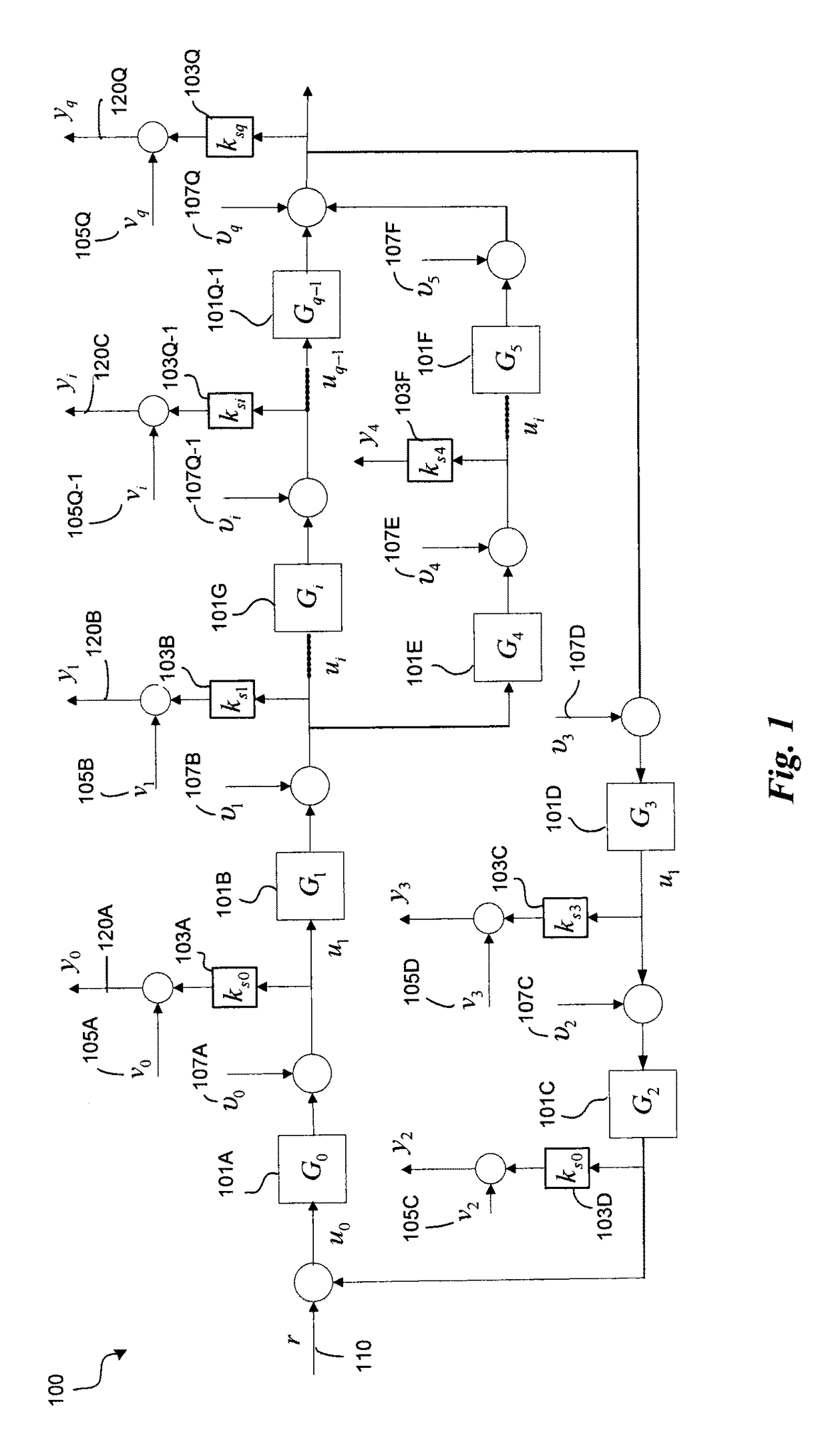
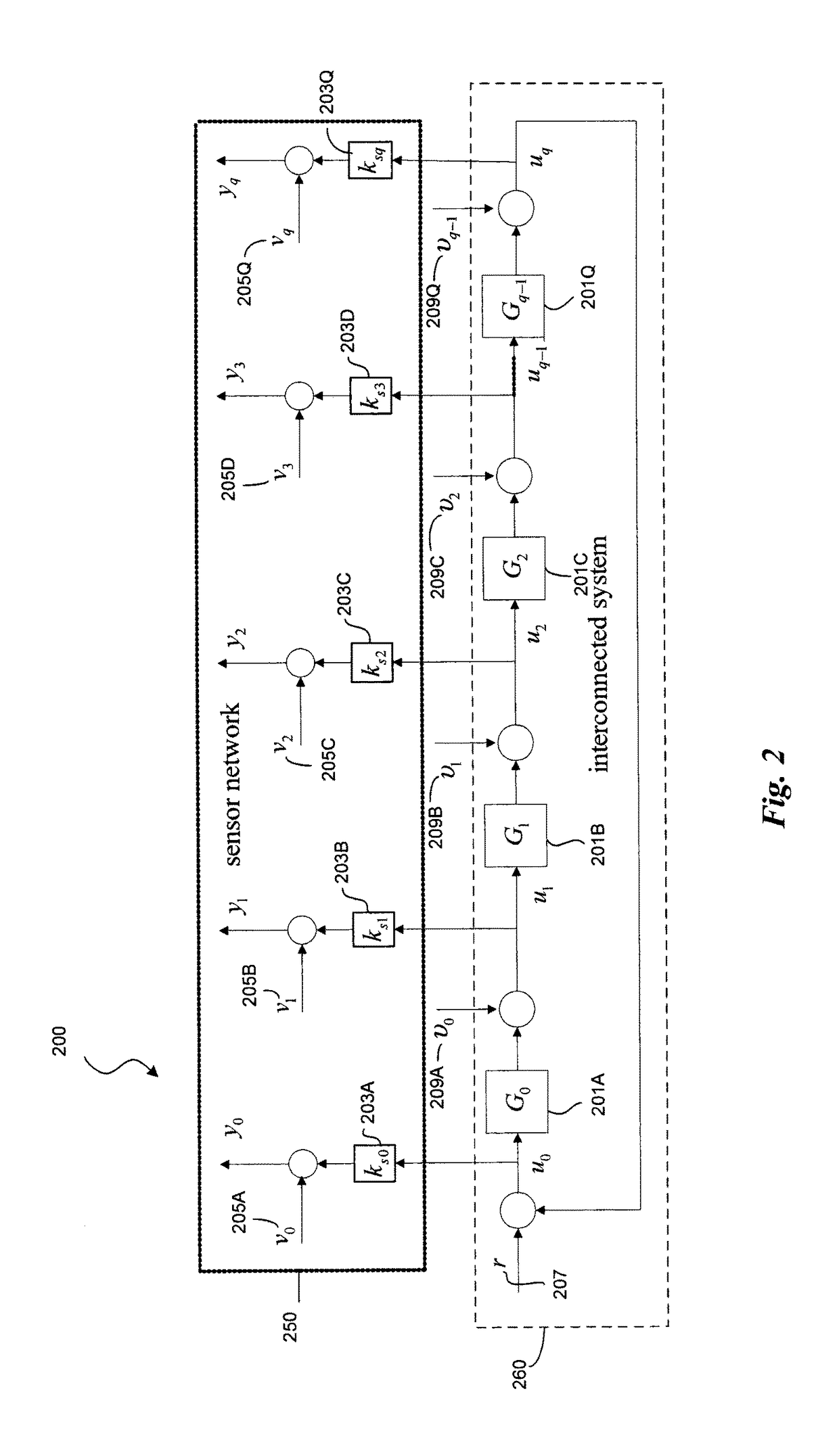
[0026]FIG. 1 depicts according to one embodiment, an exemplary network (system) 100 that includes an interconnection of sub-systems and sensors. The sensor network 100 includes a cascade, parallel and feedback combinations of q sub-systems Gi, represented as 101A-101Q, whose individual inputs are represented as ui. Each subsystem may correspond to a physical entity such as a sensor, an actuator, a controller or other system component that is subject to variations, and may be affected by noise or disturban...


PUM


Abstract

Discussed herein are a sensor-network system and a method thereof for detecting and isolating faults occurring in sub-systems and sensors included in the network. The sub-systems and the sensor measurements are subject to noise and disturbances. A bank of Kalman-filters (KF) is used to detect and isolate the faults. Each KF is driven by either a pair of consecutive sensor measurements or a pair including a reference input and a sensor measurement. The KF residual is computed for each measurement pair and is a reliable indicator of a fault in subsystems and sensors located in the network.

Description

INCORPORATION BY REFERENCE[0001]This disclosure claims the benefit of U.S. Provisional Application No. 62 / 001,315, filed on May 21, 2014, the disclosure of which is incorporated herein by reference in its entirety.FIELD OF DISCLOSURE[0002]Embodiments described herein generally relate to fault-diagnosis mechanisms for a sensor network of a cascade, parallel and feedback combination of subsystems and sensors. Specifically, the embodiments described herein are directed to the detection and isolation of fault(s), based on Kalman filters, in any of the subsystems and sensors that are subject to disturbance and measurement noise.DESCRIPTION OF THE RELATED ART[0003]The background description provided herein is for the purpose of generally presenting the context of the disclosure. Work of the presently named inventors, to the extent the work is described in this background section, as well as aspects of the description that may not otherwise qualify as prior art at the time of filing, are n...

Claims


Application Information

Patent Timeline
Patent Type & Authority Patents(United States)
IPC IPC(8): G01R31/02G01D21/00H04W84/18H04Q9/00G08C25/00G01R31/50
CPCG01R31/02G01D21/00H04Q9/00H04W84/18G08C25/00H04Q2209/823G01R31/50
Inventor CHEDED, LAHOUARIDORAISWAMI, RAJAMANI
Owner KING FAHD UNIVERSITY OF PETROLEUM AND MINERALS
Why Eureka
Try Eureka