Al technical title is built by PatSnap Al team. It summarizes the technical point description of the patent document.
a technology for wiper blades and panes, which is applied in the direction of vehicle maintenance, vehicle cleaning, domestic applications, etc., can solve the problems that the glued connection can only adapt insufficiently to harsh operating conditions, and achieve the effect of reducing the height of the wiper blades
Inactive Publication Date: 2005-06-14
ROBERT BOSCH CORP
View PDF14 Cites 63 Cited by
Summary
Abstract
Description
Claims
Application Information
AI Technical Summary
This helps you quickly interpret patents by identifying the three key elements:
Problems solved by technology
Method used
Benefits of technology
[0003]In the wiper blade according to the invention, the two spring strips are respectively disposed in one of the two existing groove-like constrictions of the wiper strip so that special receiving grooves are no longer required in the top strip of the wiper strip. This reduces the height of the wiper blade without requiring a problematic glued connection between the support element and the wiper strip. Because the width of the construction groove in a partial region is greater than the thickness of the spring strips, the wiper lip can always tilt into the required drag position during wiper operation.
[0004]In this connection, it is particularly advantageous if the lateral defining surfaces of the groove-like constrictions diverge from the intermediary strip to the longitudinal sides of the wiper strip. With a corresponding matching, the spring strips can thus guide the wiper strip on the intermediary strip and simultaneously allow the wiper lip to execute its required tilting motion into the drag position.
Problems solved by technology
A glued connection of this kind can only adapt insufficiently to the harsh operating and environmental conditions—such as alternating stress, cold, heat, ozone influence, etc.,—for the wiper blade.
Method used
Image
Click on the blue label to locate the original text in one second.
Reading with bidirectional positioning of images and text.
Examples
Embodiment Construction
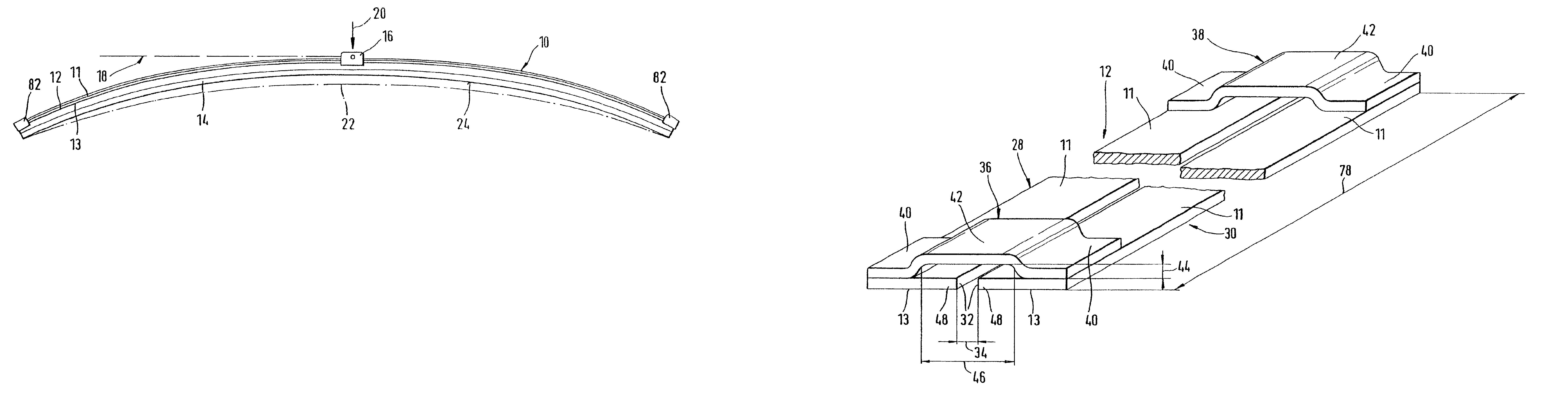
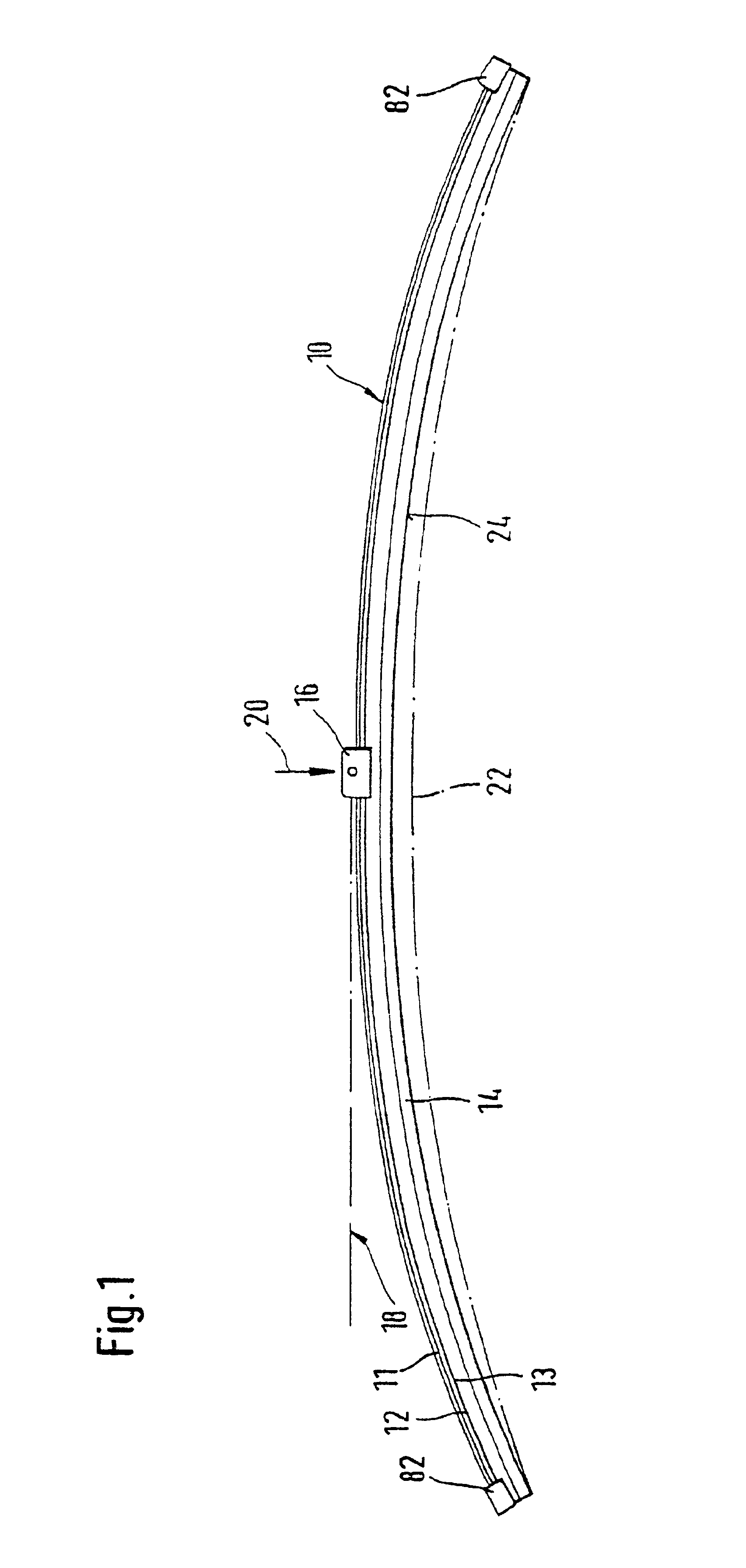
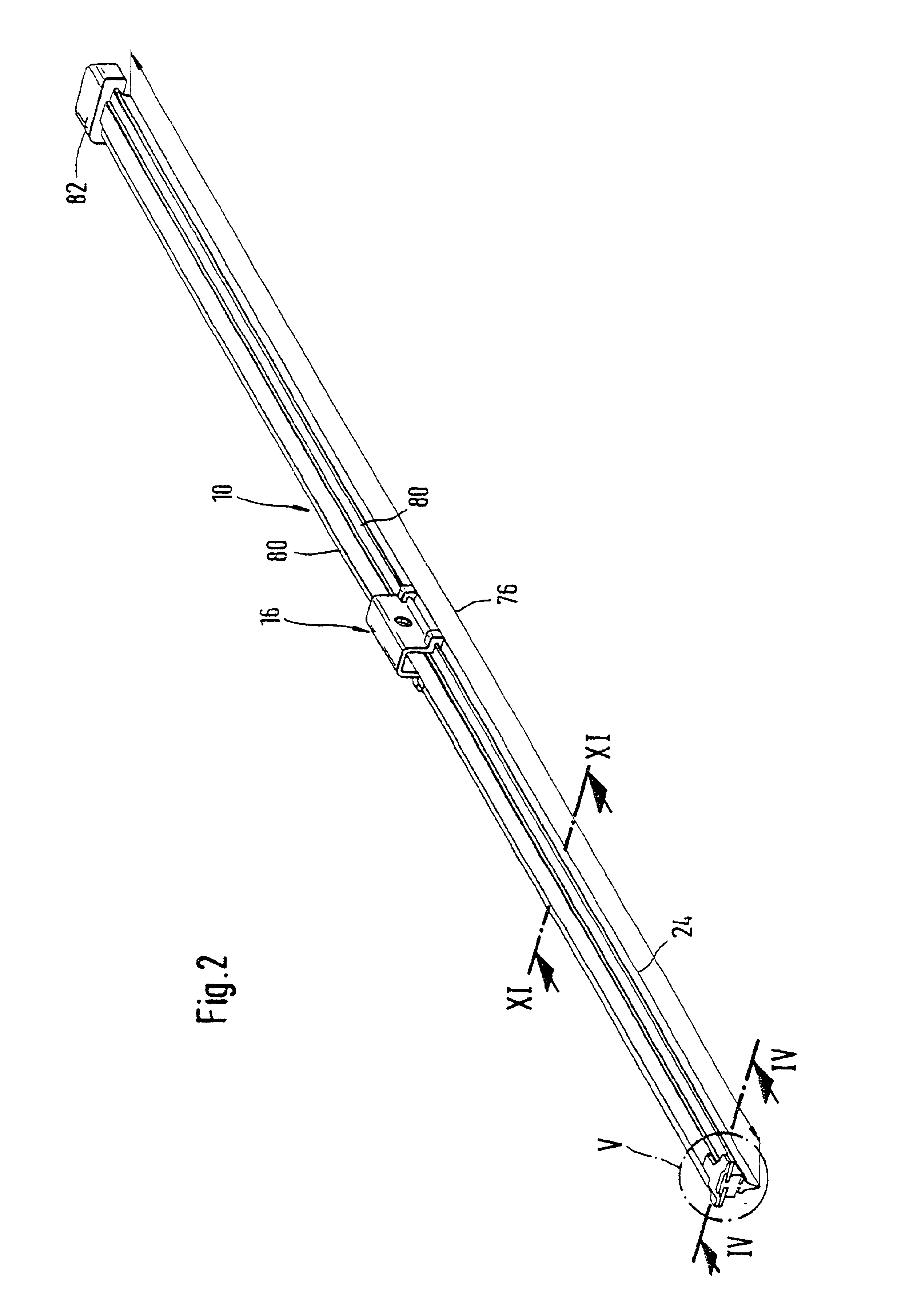
[0032]A wiper blade 10 indicated in FIGS. 1 and 2 has a band-like, elongated, spring-elastic support element 12, against whose underside 13 an elongated, rubber-elastic wiper strip 14 is disposed in a longitudinally parallel fashion. On the top side 11 of the support element 14, which is also referred to as a spring bar, the center section of this part is provided with the wiper blade part 16 of a connecting device, with the aid of which the wiper blade 10 can be detachably connected in an articulating fashion to a driven wiper arm 18 indicated with a dot-and-dash line in FIG. 1. To that end, the free end of the wiper arm 18 is provided with the wiper arm part of the connecting device. The wiper arm 18 is loaded in the direction of the arrow 20 toward the window to be wiped, for example the windshield of a motor vehicle, whose surface to be wiped is indicated with a dot-and-dash line 22 in FIG. 1. Since the line 22 is intended to represent the sharpest curvature of the window surfac...
PUM
Abstract
A wiper blade is proposed, which is used for cleaning windows, particularly of motor vehicles. The wiper blade (10) has an elongated, rubber-elastic wiper strip (14), which can be placed against the window (22) and is connected in a longitudinally parallel fashion to an elongated, spring-elastic support element (12), which has a connecting device (16) for a wiper arm (18). The wiper blade has two band-like spring strips (28, 30), which are parallel to each other and are disposed in a plane spaced a distance (26) apart from the window (22) and whose one, inner longitudinal edges (32) disposed close to each other are spaced a distance (34) apart from each other, and the wiper strip, which has a uniform cross section over its longitudinal span, has a strip-like wiper lip (102), which can be placed against the window and which, by means of a narrow intermediary strip (102) that is formed by opposing groove-like constrictions (106), is connected to a covering strip (104) secured to the support element (12), and the spring strips secure the wiper strip. A wiper blade, which is particularly low-profile and therefore insensitive to the flow conditions of the window, is obtained if each of the two inner longitudinal edges (32) of the spring strips (28, 30) is disposed in one of the two groove-like constrictions (106) of the wiper strip (100), where the width of the constriction grooves (106), at least over an outer partial region, is greater than the thickness of the spring strips (28, 30).
Description
BACKGROUND OF THE INVENTION[0001]In known wiper blades, the purpose of the support element is to assure as uniform as possible a distribution of the wiper blade pressure against the window, which pressure is exerted by the wiper arm, over the entire wiping field wiped by the wiper blade. Through an appropriate curvature of the unloaded support element—i.e. when the wiper blade is not resting against the window—the ends of the wiper strip, which is placed completely against the window during operation of the wiper blade, are loaded toward the window by the support element, which is stretched in this state, even though the curvature radii of spherically curved vehicle windows change with each wiper blade position. The curvature of the wiper blade must therefore be somewhat sharper than the sharpest curvature measured within the wiping field on the window to be wiped. The support element consequently replaces the expensive support bracket structure with two spring strips disposed in th...
Claims
Application Information
Patent Timeline
Application Date:The date an application was filed.
Publication Date:The date a patent or application was officially published.
First Publication Date:The earliest publication date of a patent with the same application number.
Issue Date:Publication date of the patent grant document.
PCT Entry Date:The Entry date of PCT National Phase.
Estimated Expiry Date:The statutory expiry date of a patent right according to the Patent Law, and it is the longest term of protection that the patent right can achieve without the termination of the patent right due to other reasons(Term extension factor has been taken into account ).
Invalid Date:Actual expiry date is based on effective date or publication date of legal transaction data of invalid patent.