Cuff lock and push-button locking mechanism

Inactive Publication Date: 2005-06-14
MASTER LOCK COMANY LLC
View PDF17 Cites 21 Cited by
  • Summary
  • Abstract
  • Description
  • Claims
  • Application Information

AI Technical Summary

Benefits of technology

[0005]The invention provides in a second aspect a cylinder lock comprising a housing having a rotatable plug rotatably disposed therein and a fixed plug secured to said housing. The non-rotatable shaft is slidably mounted within the housing and is slidable between a locked position and an unlocked position. The non-rotatable shaft includes an actuated end extending from an end of said housing and a latching end extending from an opposite end of said housing. One or more tumbler pins are received in one or more axially aligned bores of the fixed plug and the rotatable plug; and one or more retaining elements are po

Problems solved by technology

Prior art bicycle locks typically are made of metal and generally have a large inflexible U shape which are bulky in size.
Further, prior art bicycle locks generally require a key to both lock and unlock the lock.
Another disadvantage to prior art bicycle locks is that they require two hands to operate the lock.
Yet another disadvantage to prior art bicycle locks is that they

Method used


Image

  • Cuff lock and push-button locking mechanism
  • Cuff lock and push-button locking mechanism
  • Cuff lock and push-button locking mechanism

Examples


Embodiment Construction

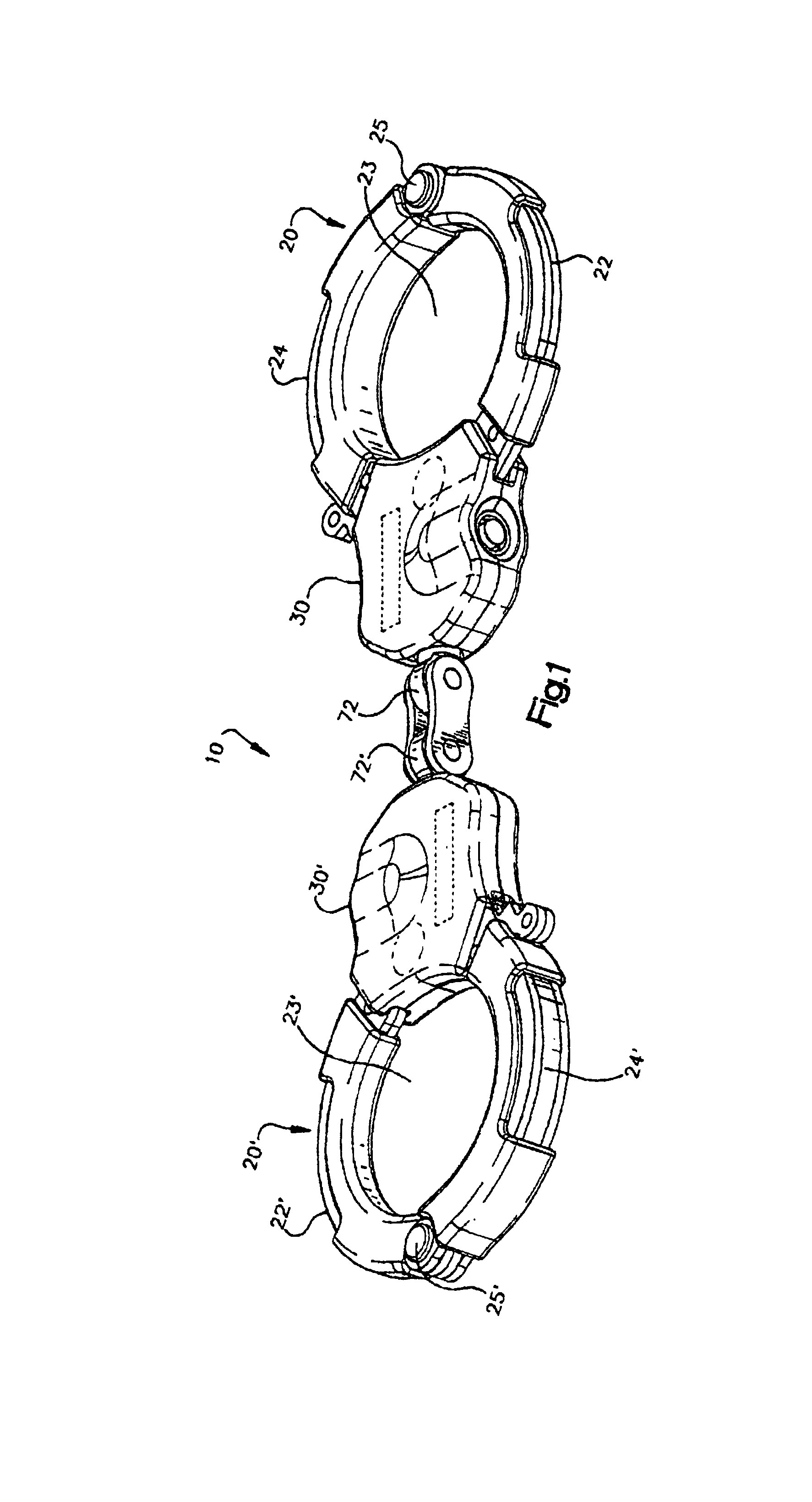
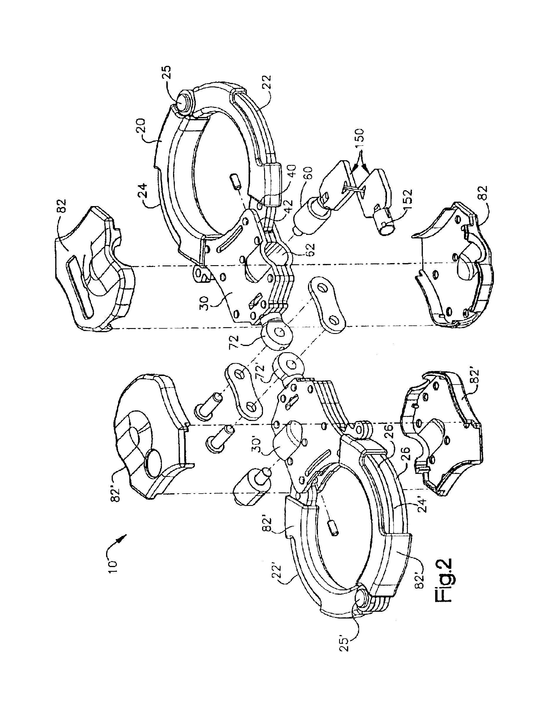
[0022]The cuff lock as shown generally at 10, is useful for securing articles such as the frame of a bicycle and front tire to a fixture such as a pole. However, the invention is not limited to such use, as there are many other uses readily apparent to those skilled in the art. The cuff lock 10 comprises a first and second cuff 20, 20″, and a first and second lock body housing 30,30″, wherein the lock bodies are connected together as described in more detail, below.

[0023]Each cuff 20,20″ comprises a swing arm 22,22″ and a stationary arm 24,24″ which are pivotally connected together. The swing arm 22 and the stationary arm 24 preferably are curved, and when joined together and in cooperation with the lock body housing form a circular hole 23. The stationary arm is preferably comprised of two or more metal stampings 26 mechanically fastened together. The metal stampings 26 may optionally include the stationary arm 24 and the lock body housing 30 formed as a integral piece. The station...


PUM


Abstract

The invention provides a pair of cuff locks joined by a universal joint and linkage system which provides for 360 relative rotation between the cuffs as well as allow the cuffs to be folded together into a compact position. The invention further provides for a push button cylinder lock which includes a rotatable plug and a fixed plug each having a plurality of aligned bores for receiving one or more tumbler pins. The push button cylinder lock further includes a non-rotatable push button shaft which is sildably mounted within the housing. One or more retaining pins engage locking indents of the push button shaft.

Description

CROSS REFERENCE TO RELATED APPLICATIONS[0001]This application is a divisional of commonly owned application Ser. No. 10 / 038,095 filed Jan. 4, 2002, now abandoned which claims the benefit of U.S. Provisional Application No. 60 / 259,966, filed on Jan. 4, 2001.BACKGROUND OF INVENTION[0002]The invention provides an improved design for securing personal objects such as a bicycle or other personal objects such as a portable computer. Prior art bicycle locks typically are made of metal and generally have a large inflexible U shape which are bulky in size. Further, prior art bicycle locks generally require a key to both lock and unlock the lock. Another disadvantage to prior art bicycle locks is that they require two hands to operate the lock. Yet another disadvantage to prior art bicycle locks is that they are not adjustable in size to accommodate the object to be secured. Thus an improved bicycle lock is desired which overcomes the above described disadvantages.[0003]The invention further ...

Claims


Application Information

Patent Timeline
IPC IPC(8): E05B13/00E05B13/10E05B27/00E05B27/08E05B75/00E05B15/00
CPCE05B13/105E05B75/00E05B27/083E05B15/0046Y10T70/7853Y10T70/404Y10T70/7751Y10T70/7593
Inventor MAKOS, TIMOTHYELLIOTT, JOSEPHGRANDY, SR., KENNETH N.YIP, VICTOR
Owner MASTER LOCK COMANY LLC
Why Eureka
Try Eureka