Marine time-lapse seismic surveying

Active Publication Date: 2005-06-14
SHELL USA INC
View PDF9 Cites 38 Cited by
  • Summary
  • Abstract
  • Description
  • Claims
  • Application Information

AI Technical Summary

Benefits of technology

[0009]To this end the method of marine time-lapse seismic surveying the subsurface, using a seismic source and a seismic receiver system. The source and receiver systems are positioned at known locations. A seismic data set is generated comprised of at least two signals at each receiver in response to at least two seismic sound waves, the sound waves being transmitted at two different sea states but, proximate in time such that changes in the subterranean formation would be negligible. In receiving the signal set, one can determine the two-way water travel times. After a predetermined time, in which it is expected that the subterranean formation conditions will have changed, the seismic source(s) and receiver(s) are positioned at the same place whe

Problems solved by technology

Other factors that adversely affect the accuracy of time-lapse surveys in a m

Method used


Image

  • Marine time-lapse seismic surveying
  • Marine time-lapse seismic surveying
  • Marine time-lapse seismic surveying

Examples


Embodiment Construction

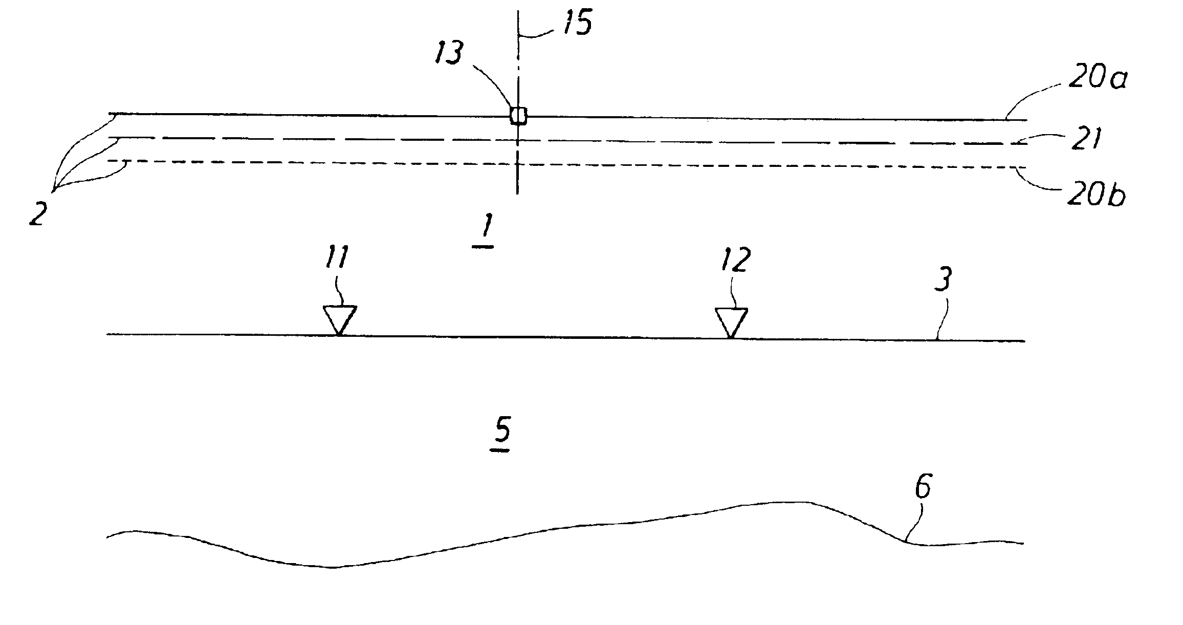
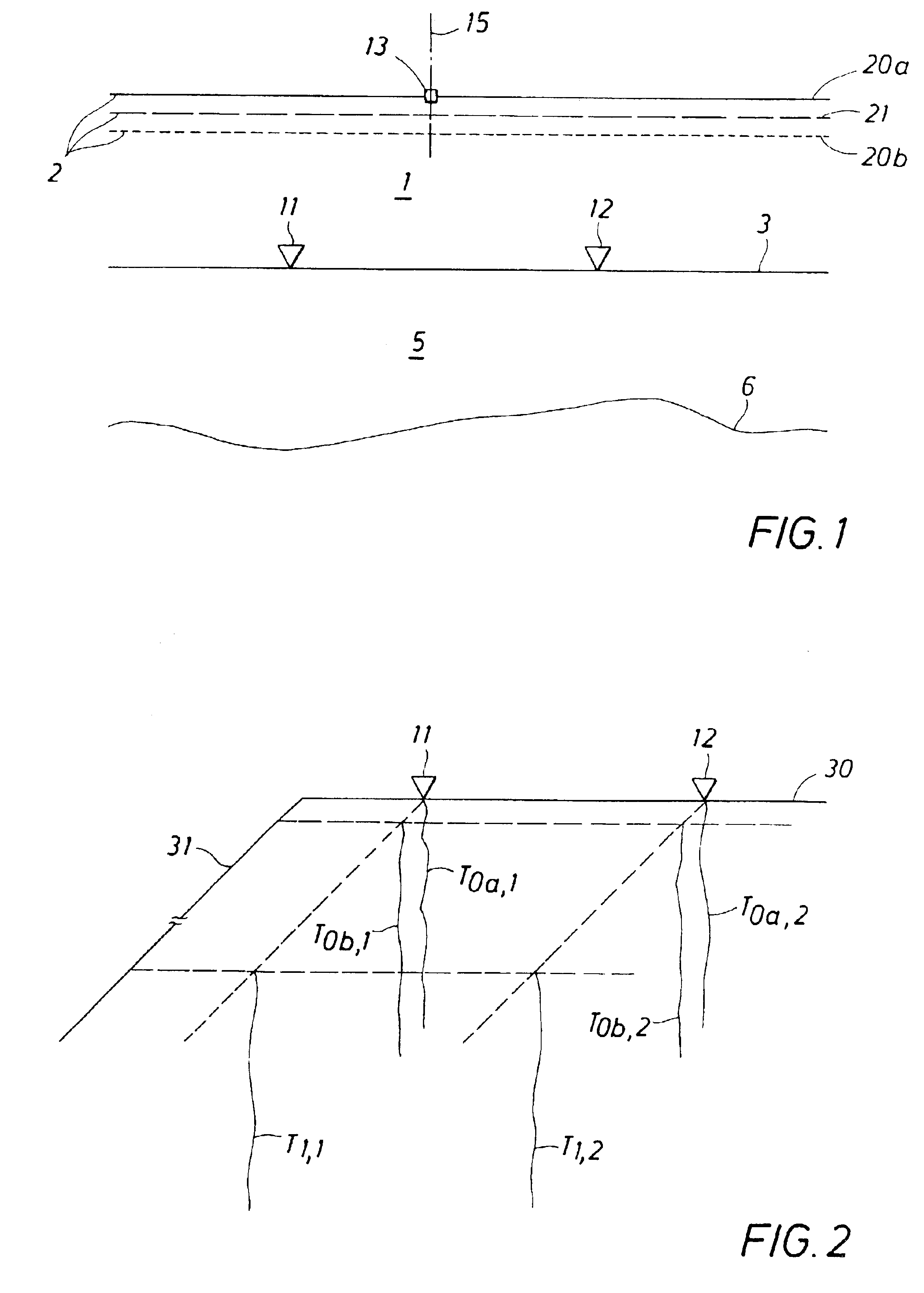
[0021]Reference is now made to FIG. 1. The method according to the present invention is a method of carrying out at sea a time-lapse survey of the subsurface. In FIG. 1 is shown schematically a body 1 of water representing the sea bounded by a sea surface 2 and a sea bottom 3, and the subsurface 5 below the sea bottom 3. Which subsurface 5 contains at least one reflector 6.

[0022]In the method according to the invention a seismic receiver system comprising at least one seismic receiver is located at a predetermined position. In FIG. 1 the seismic receiver system comprises two seismic receivers 11 and 12, and the receiver location having a predetermined position is at the sea bottom 3.

[0023]The first step of the method is positioning a seismic source 13 at a source location having a predetermined position 15. The position 15 is the horizontal position of the source, which is the longitude-latitude position of the seismic source 13. The horizontal position of the source is schematicall...


PUM


Abstract

A method for making a time-lapse seismic survey in a marine environment, the method designed to eliminate multiple surface reflections and changes in sea state and conditions. Seismic sources and receivers are positioned at predetermined conditions for a first set of data in which at least two sets of seismic signals are recorded at each receiver, proximate in time, such that there are insignificant changes in the subsurface formation. At a later point in time the seismic source(s) and receiver(s) are positioned at the same place when the first seismic data set was generated. A seismic source emits a sound wave and the seismic receiver receives what will be called a “monitor signal” and the two-way water travel time is again determined. A model is then developed for the first and second seismic data sets in that includes the subsurface signal, changes in the subsurface signal and the effect of multiple reflections. A set of filter functions are then developed to filter out the multiple reflections based on the two-way water travel times of the first seismic data set. The first seismic data set, the second seismic data set and the filter function are then used to calculate the differences in the subsurface layers over the elapsed period of time between the two seismic data sets.

Description

PRIORITY CLAIM[0001]The present invention claims priority on U.S. Provisional Application 60 / 372,960, filed 16 Apr. 2002.FIELD OF THE INVENTION[0002]The present invention relates to time-lapse seismic surveying of a subterranean formation, more particularly, a method for time lapse-marine surveying in which changes in sea-state between survey sets are filtered to provide more accurate information regarding changes in the subterranean formation.BACKGROUND OF THE INVENTION[0003]Time-lapse seismic surveying or monitoring involves obtaining seismic data of the same part of the subterranean formation at different times. It allows studying the changes in seismic properties of the formation as a function of time due to for example fluid flow through the underground formation, spatial and temporal variation in fluid saturation, pressure and temperature. Seismic data can be combined to generate images that show the changes. The time-lapse seismic surveying technique has applications such as ...

Claims


Application Information

Patent Timeline
IPC IPC(8): G01V1/36G01V1/28G01V1/38
CPCG01V1/364G01V1/3808G01V1/38G01V2210/56
Inventor CALVERT, RODNEY WILLIAM
Owner SHELL USA INC
Why Eureka
Try Eureka