Multistage air cleaner including pulse cleaning system

a technology of air cleaners and pulses, applied in the field of air cleaners, can solve the problems of generating unique problems for air cleaner operation, affecting the operation of certain very large and powerful equipment types, and affecting the operation of certain air cleaners

Inactive Publication Date: 2005-06-21
DONALDSON CO INC
View PDF31 Cites 109 Cited by
  • Summary
  • Abstract
  • Description
  • Claims
  • Application Information

AI Technical Summary

Problems solved by technology

In time, the filter element(s) becomes occluded or loaded with a concomitant increase in restriction across the air cleaner.
Certain very large and powerful equipment types generate unique problems with respect to air cleaner operation.
Such equipment operates for extended periods in extremely dusty environments.
Such equipment also has very large volume demands for combustion air.
This means very large amounts of particle-laden air on an almost continuous basis is passing through the air cleaner system.

Method used


Image

  • Multistage air cleaner including pulse cleaning system
  • Multistage air cleaner including pulse cleaning system
  • Multistage air cleaner including pulse cleaning system

Examples


Embodiment Construction

I. Disclosure of U.S. patent application Ser. No. 09 / 325,697

[0061]A. Environment of Use; System Demand

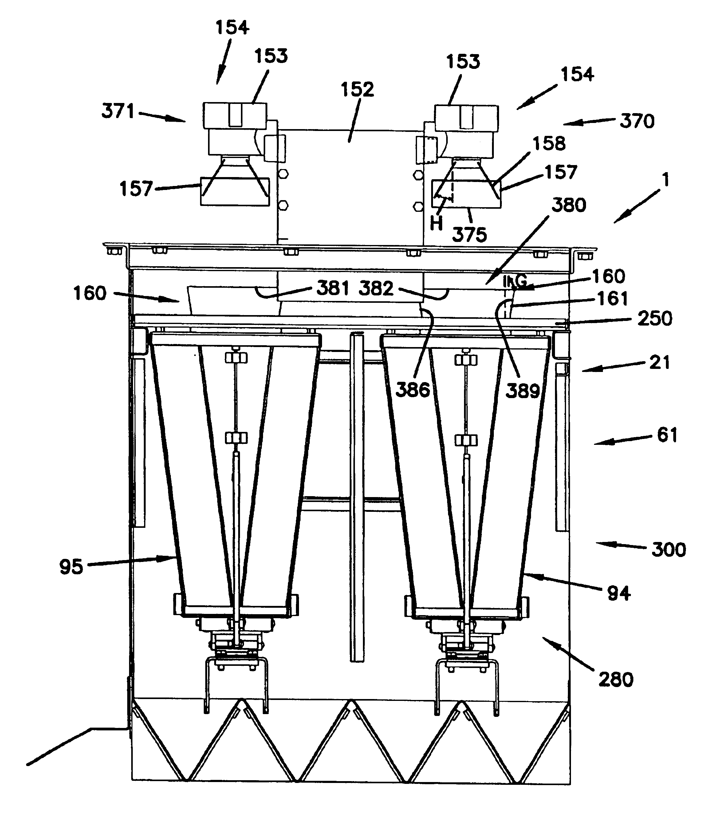
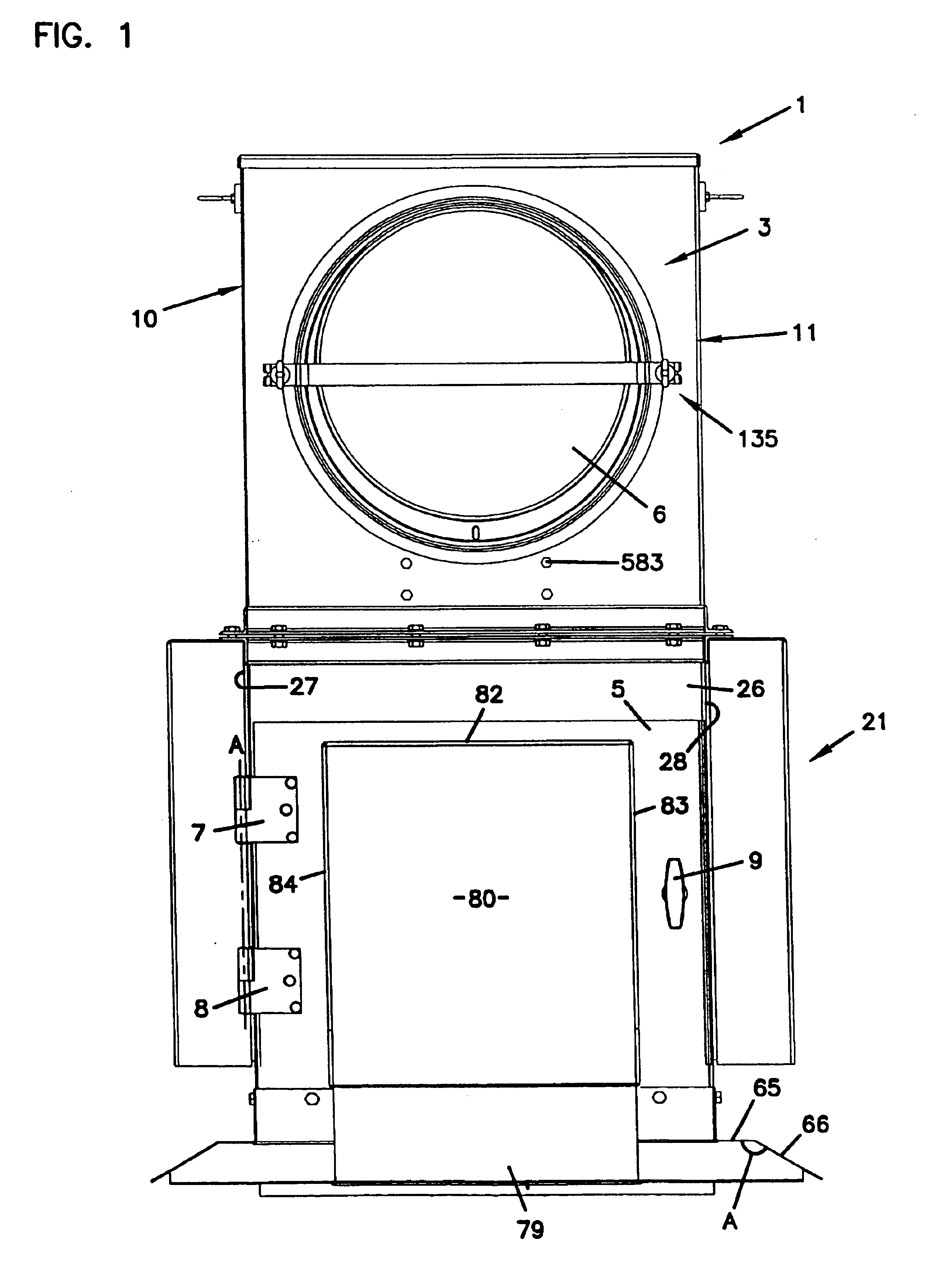
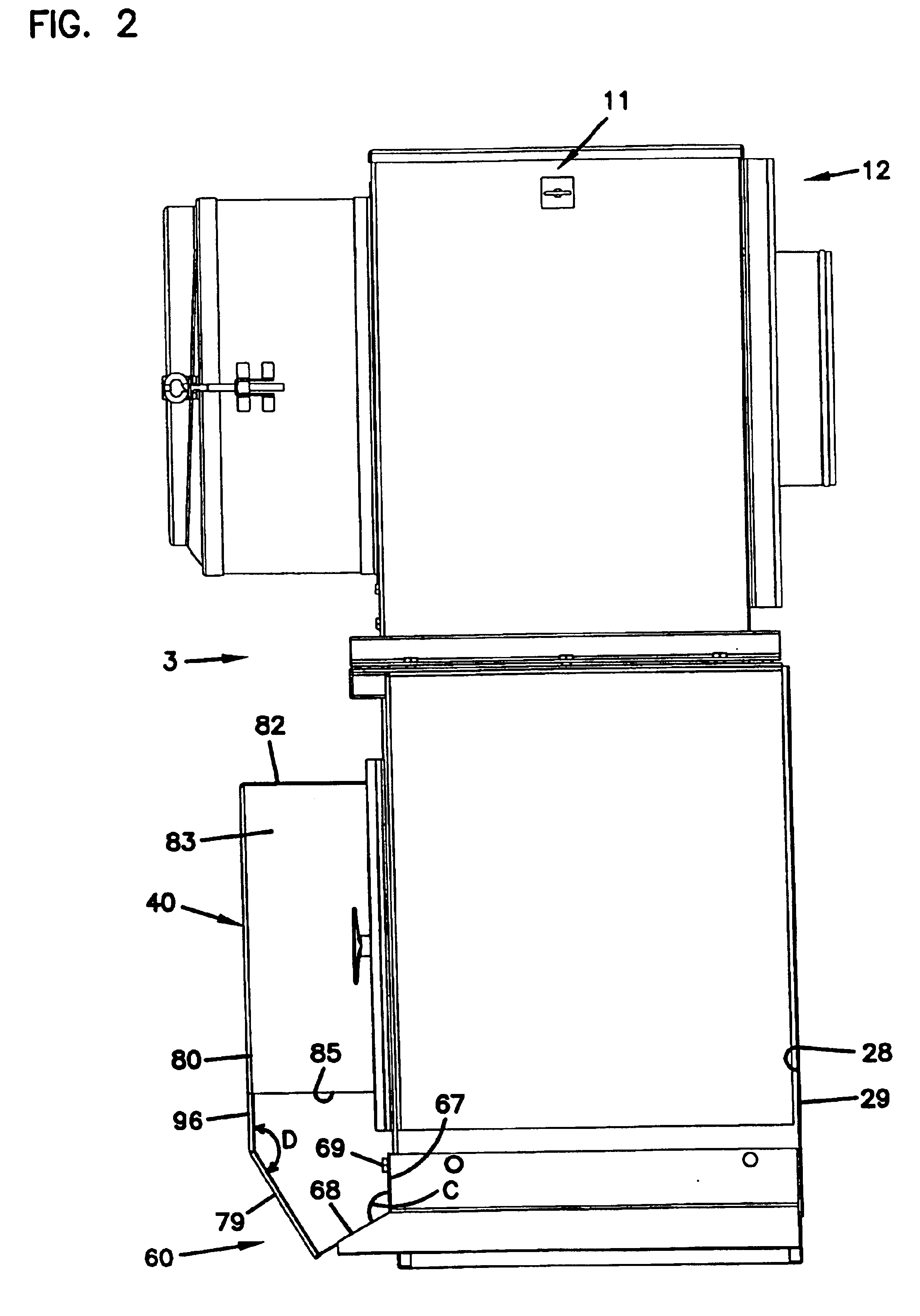
[0062]The arrangements depicted in drawings 1-35 and described in U.S. patent application Ser. No. 09 / 325,697, and the principles defined in association with them, were specifically designed for advantageous application in certain types of equipment and work environments. While the principles could be applied in a variety of alternate applications, the unique arrangements described are particularly advantageous for the identified systems of use.

[0063]According to U.S. Ser. No. 09 / 325,697, typical systems in which equipment of the type defined therein will be useful are engine applications concerning large engines, typically 500 to 2,000 hp (37.3-149.2 KW). Such engines are generally defined by air flow demands on the order of about 1,300 to 4,500 cfm (81,000 to 281,000 pwm).

[0064]According to U.S. Ser. No. 09 / 325,697, in general, it is desirable that such equipment be able to operat...


PUM

PropertyMeasurementUnit
pressureaaaaaaaaaa
anglesaaaaaaaaaa
angleaaaaaaaaaa

Abstract

A V-pack filter includes a frame construction having a first frame structure and a second frame structure. The V-pack filter also includes first and second panel sections mounted in extension between the first and second frame structures. The first panel section has first and second ends. The second panel section has third and fourth ends. The first and third ends have a first distance therebetween while the second and fourth ends have a second distance therebetween. The second distance is generally greater than the first distance. The first and second panel sections and the second frame structure define an air flow aperture. A seal arrangement circumscribes the air flow aperture and projects outwardly from the second frame structure. The first frame structure defines a first receiver indent. Assemblies and methods are also included.

Description

[0001]This application is a divisional application of application Ser. No. 09 / 980,270, filed Apr. 12, 2002, now U.S. Pat. No. 6,676,721, which is a 371 of International application serial no. PCT / US00 / 15436, filed Jun. 2, 2000, which claims the benefit of U.S. application Ser. No. 09 / 325,697 filed Jun. 3, 1999 and Ser. No. 09 / 452,311 filed Dec. 1, 1999.FIELD OF THE INVENTION[0002]The present disclosure relates to air cleaners and particularly concerns air cleaners for cleaning combustion air directed to the engine air intake of large vehicles and equipment. The disclosure concerns preferred designs of air cleaners for such use, and methods of assembly and use.BACKGROUND OF THE INVENTION[0003]In general, combustion air for engines needs to be filtered to prevent particulates, otherwise carried in the intake air stream, from reaching sensitive engine components. As a result, nearly every engine system involving combustion air includes an air cleaner assembly of some type positioned in...

Claims


Application Information

Patent Timeline
Patent Type & Authority Patents(United States)
IPC IPC(8): B01D46/24B01D46/00B01D46/10
CPCB01D46/0005B01D46/002B01D46/0068B01D46/0086B01D46/10B01D46/125F02M35/08B01D46/46F02M35/024B01D46/4227B01D2265/024B01D2265/025B01D2277/20B01D2279/60B01D46/58B01D46/71B01D46/121
Inventor GILLINGHAM, GARY R.KOEHLER, STAN M.KRISKO, WILLIAM J.MILLER, THOMAS G.OLSON, WINSTON E.WAHLQUIST, FRED H.FUCHS, ERVIN P.WILSON, EUGENE D.
Owner DONALDSON CO INC
Why Eureka
Try Eureka