Disk device conducting a disturbance compensation based on a time-interval measurement in reading servo sectors recorded on a disk

a disk device and time-interval measurement technology, applied in the field of disk devices and a method of compensating a disturbance in the disk device, can solve the problems of complicated structure and increasing the cost of the conventional magnetic disk devi

Inactive Publication Date: 2005-06-21
TOSHIBA STORAGE DEVICE CORP
View PDF25 Cites 47 Cited by
  • Summary
  • Abstract
  • Description
  • Claims
  • Application Information

AI Technical Summary

Benefits of technology

The technical effect of this patent is to improve the performance of a disk device by providing better control over its operation and reducing disturbances that may affect it. This includes methods for detecting and measuring these disturbances, identifying their causes, and developing ways to mitigate them. Overall, this results in more reliable and efficient use of disk devices in various applications such as data storage and retrieval.

Problems solved by technology

The technical problem addressed in this patent is how to improve the performance and reduce costs associated with magnetic disk devices used for data storage. Specifically, it proposes a solution for compensating disturbances caused by external factors such as temperature variations during operation without requiring expensive accelerometers or complex structures.

Method used


Image

  • Disk device conducting a disturbance compensation based on a time-interval measurement in reading servo sectors recorded on a disk
  • Disk device conducting a disturbance compensation based on a time-interval measurement in reading servo sectors recorded on a disk
  • Disk device conducting a disturbance compensation based on a time-interval measurement in reading servo sectors recorded on a disk

Examples


Embodiment Construction

[0082]A description will now be given, with reference to the drawings, of an embodiment according to the present invention.

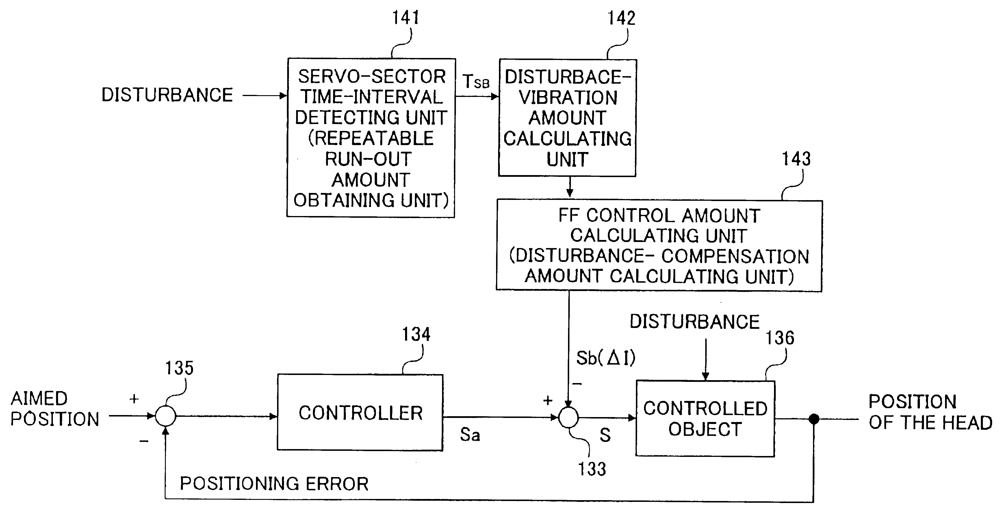
[0083]As described hereinafter, the present embodiment conducts a disturbance compensation by measuring a time interval of a servo sector and calculating an amount of a disturbance vibration based on an erroneous amount relative to a reference value of the time interval of the servo sector.

[0084]Then, a description will first be given of a disk format of a magnetic disk device.

[0085]FIG. 5A is an illustration of a disk format.

[0086]The magnetic disk 111 has servo sectors SB0 to SBn formed at a constant servo-sector interval t0. The servo sectors SB0 to SBn are recorded beforehand by a servo track writer (STW). Each of the servo sectors SB0 to SBn includes a servo sync mark SM, a cylinder number CYL, a positional information POS, as shown in FIG. 5B. Each of the servo sectors SB0 to SBn is recognized when the servo sync mark SM is detected. Accordingly, a servo-s...


PUM


Abstract

A disk device comprises a disk having predetermined information sectors recorded at a constant interval; a head scanning the disk; and a disturbance-compensation unit obtaining an amount of a disturbance based on a time-interval measurement in reading the predetermined information sectors so as to compensate a position of the head according to the amount of the disturbance.

Description


Claims


Application Information

Patent Timeline
Owner TOSHIBA STORAGE DEVICE CORP
Why Eureka
Try Eureka