Structural framing members with integrated flow channels and method of making same

a technology of structural framing members and flow channels, applied in the field of composite structures, can solve the problems of labor and material cost, and cannot be completely solved

Inactive Publication Date: 2005-06-28
COMPOSITES INTELLECTUAL HLDG INC
View PDF8 Cites 23 Cited by
  • Summary
  • Abstract
  • Description
  • Claims
  • Application Information

AI Technical Summary

Benefits of technology

[0011]Alternatively, the fabric may be polyester staple mat, glass fiber mat, organic fiber mat or inorganic fiber mat. The structural foam used herein for the foam core can be a two-part, self-expa

Problems solved by technology

One issue with closed mold manufacturing techniques involves the problem of ensuring adequate resin distribution over the whole laminate sufficiently quickly before the resin has cured substantially.
However, the additi

Method used


Image

  • Structural framing members with integrated flow channels and method of making same
  • Structural framing members with integrated flow channels and method of making same
  • Structural framing members with integrated flow channels and method of making same

Examples


Embodiment Construction

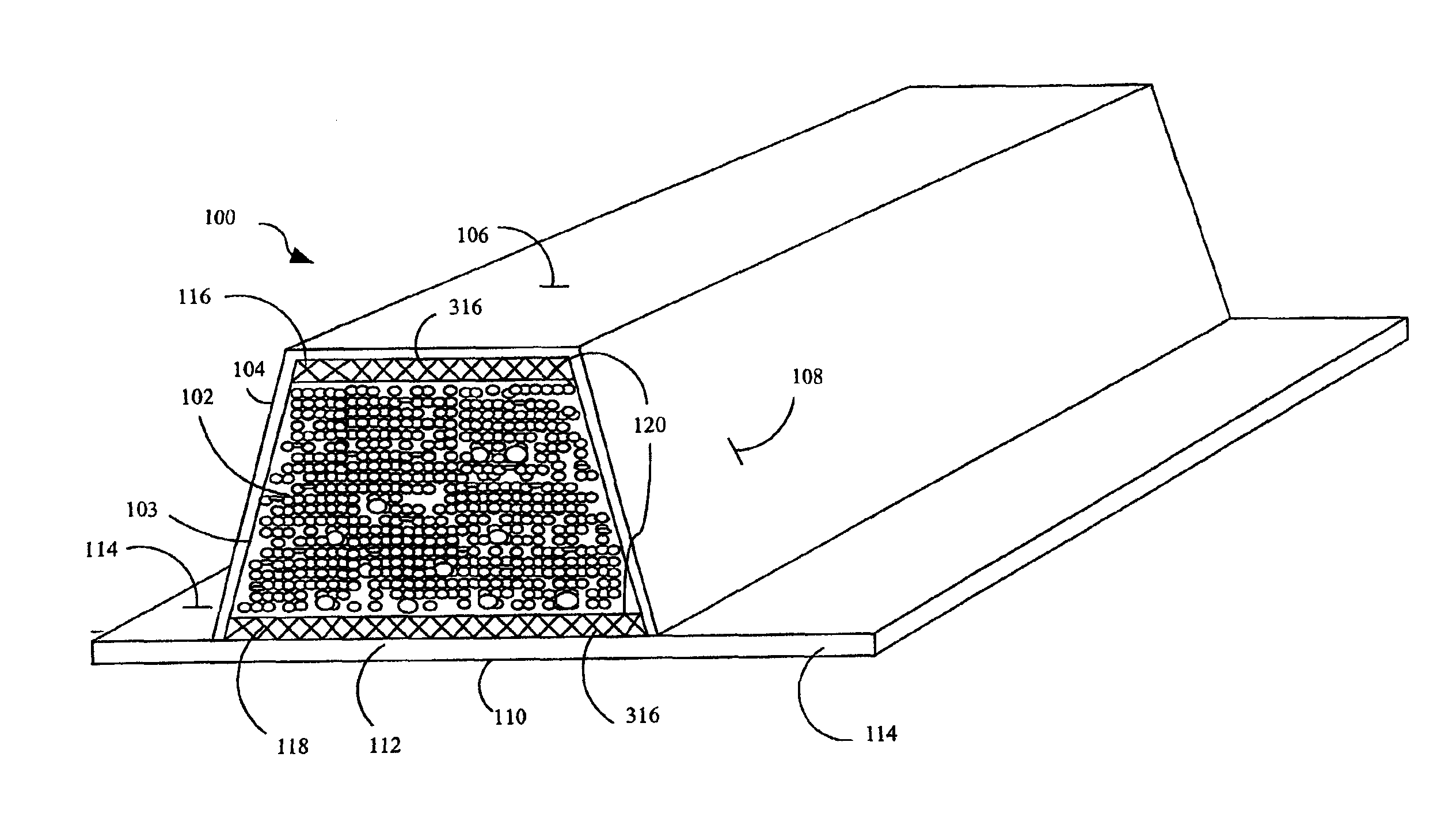
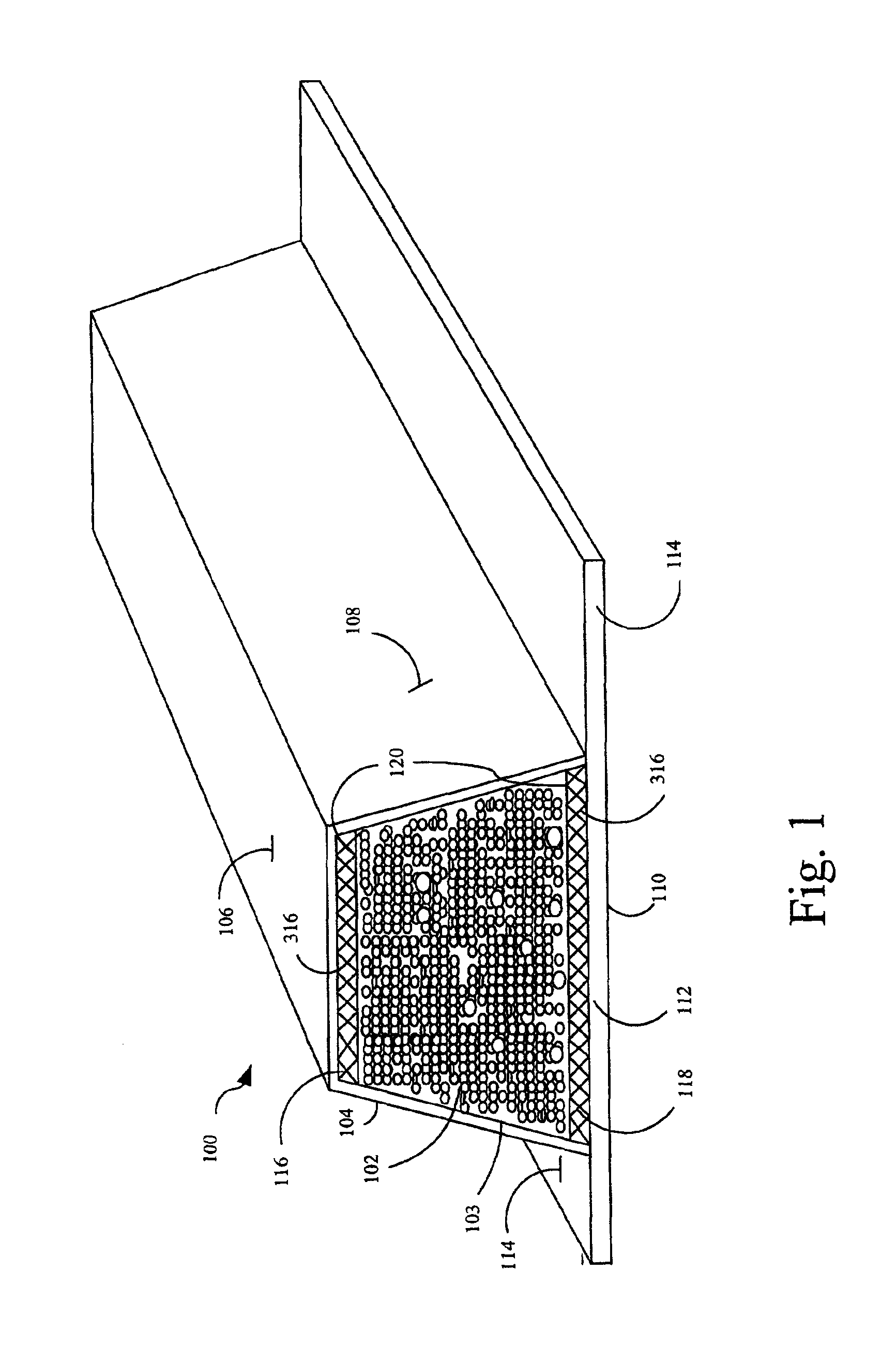
[0018]FIG. 1 is a drawing useful for explaining the composite part according to a preferred embodiment of the invention. Composite part 100 comprises an elongated foam core 102 and a flow channel 316 formed by flow channel media 116 attached thereto along a first elongated side 106. A fabric layer 103 is secured to the elongated foam core 102 and encloses at least the elongated side 106 of the foam core 102. In this way, the fabric layer 103 and the flow channel media 116 define a resin flow path along the elongated side 106 of the composite part 100.

[0019]One or more additional flow channels can be provided on other elongated sides 104, 108, 110 of the composite part 100. According to a preferred at least a second flow channel can be provided along a side 110 of the composite part 100 forming a base thereof and opposed from the flow channel media 116. The second flow channel is comprised of a flow channel media 118 and can be enclosed by fabric layer 103 or a separate fabric layer ...


PUM

PropertyMeasurementUnit
Fractionaaaaaaaaaa
Fractionaaaaaaaaaa
Fractionaaaaaaaaaa

Abstract

The invention concerns a composite part, comprising an elongated foam core and a flow channel media attached to a first elongated side thereof. The flow channel media forms interstices for the passage of resin. At least one fabric layer is secured to the elongated foam core, and encloses a first elongated side of the foam core, including the flow channel media. In this way, a resin flow path is defined along the first elongated side. The fabric layer can further enclose at least a second and third elongated side of the foam core where, where each of the second and third elongated sides adjoin the first elongated side. Fabric tab portions can be provided extending from the second and third elongated sides for aiding in the installation of the composite part in a larger composite structure.

Description

BACKGROUND OF THE INVENTION[0001]1. Technical Field[0002]The invention relates generally to the field of composite structures, and more particularly to the framing members with integrated flow channels for use in certain manufacturing processes.[0003]2. Description of the Related Art[0004]A variety of manufacturing techniques are known for assembling composite structures. For example, the spray lay-up method has been used for many years with good success. In spray lay-up systems, chopped fiber together with a catalyzed resin is sprayed directly into an open mold. Structural reinforcing members such as stringers can be positioned in the mold prior to the application of the chopped fiber and resin for improving the overall strength and rigidity of the structure. For example, U.S. Pat. Nos. 5,429,066, 5,800,749 and 5,664,518 to Lewit et al. describe various types of reinforcing members that can be used for this purpose. The fiber, resin and stringers applied in this way are then left t...

Claims


Application Information

Patent Timeline
IPC IPC(8): B29C44/38B29C44/02B29C44/12B29C44/34B32B27/12B29C70/04B29C70/08B29C70/48B32B5/18B29C70/54
CPCB29C44/1209B29C44/385B29C70/086B29C70/48B32B5/18B32B27/12B29C70/547Y10T428/237Y10T428/239Y10T428/233Y10T428/249953Y10T428/249955Y10T428/249958Y10T428/249981
Inventor LEWIT, SCOTT M.JOHNSON, KEITH G.
Owner COMPOSITES INTELLECTUAL HLDG INC
Why Eureka
Try Eureka