Gimballed reflector mounting platform

a technology for mounting platforms and reflectors, which is applied in the field of mounting platforms for reflectors, can solve the problems of increasing the size of the first motor required, increasing the complexity and cost of the device, and requiring motors with considerably more torqu

Active Publication Date: 2005-06-28
CALLAHAN CELLULAR L L C
View PDF16 Cites 47 Cited by
  • Summary
  • Abstract
  • Description
  • Claims
  • Application Information

AI Technical Summary

Problems solved by technology

Specifically, the aforementioned fully adjustable systems have a large height profile requiring extra supporting structure, which adds to the complexity and cost of the device.
Moreover, the first motor must support the mass of the antenna, as well as the mass of the second motor, which greatly increases the size of the first motor required.
Furthermore, the center of gravity of a conventional antenna is usually offset from the pivot points, thereby requiring motors with considerably more torque.
Unfortunately, when these devices are mounted in any position other than the vertical position illustrated in the patents, the antenna's center of mass would be far from the main support, which results in the base motor having to support the entire mass of the antenna, and, in some cases, the mass of the upper motor, as well.
Furthermore, in pulley and wire systems the pull strings are the weakest link, which, when broken, disable the system and potentially cause uncontrolled movement.
Relatively complex alternatives have also been developed, but these involve complicated mechanical structures, requiring high manufacturing costs.

Method used


Image

  • Gimballed reflector mounting platform
  • Gimballed reflector mounting platform
  • Gimballed reflector mounting platform

Examples


Embodiment Construction

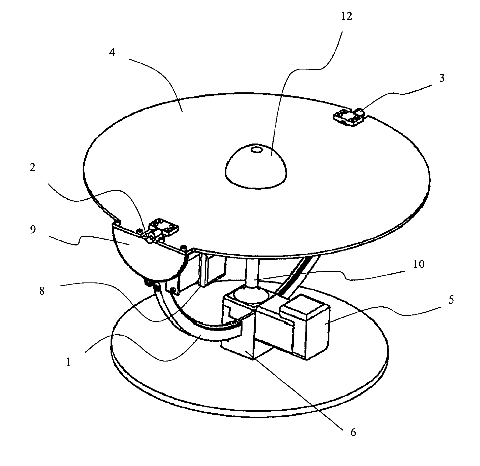
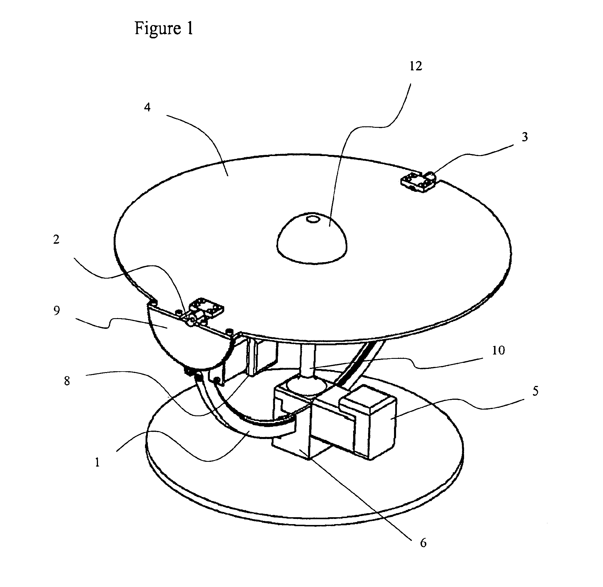
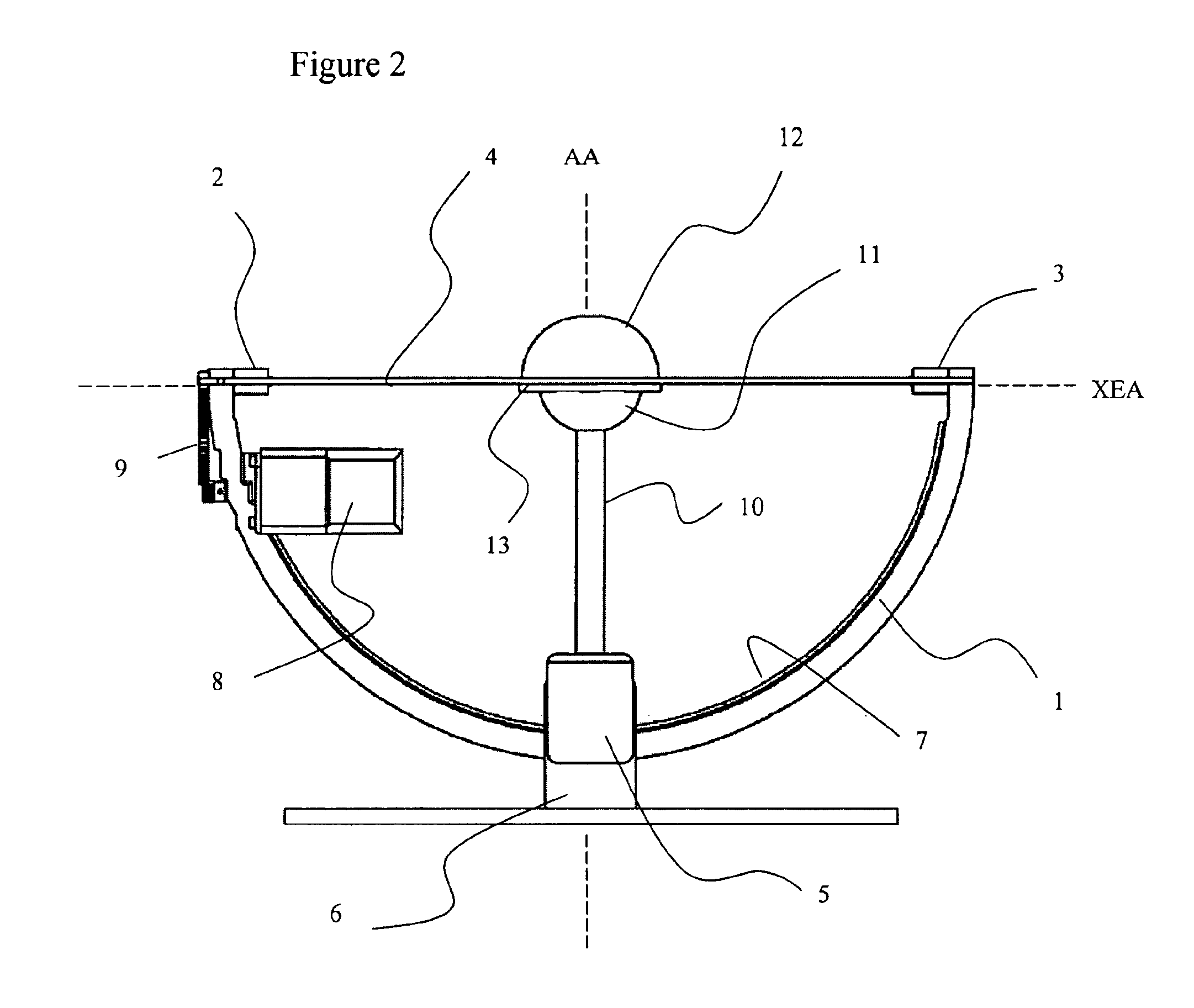
[0020]The reflector mounting platform according to the present invention includes a semicircular yoke 1 rotatable about a fixed elevation axis EA. Bearings 2 and 3 are mounted on either end of the yoke 1 for pivotally supporting a flat plate (or parabolic dish) reflector 4 about a pivotable cross-elevation axis XEA. With reference to FIG. 5, as the reflector 4 is steered, the transmitted or received beam is steered in a direction perpendicular to the aperture of the reflector 4. An elevation angle θE is measured by rotation about the elevation axis EA (the y axis). Similarly, a cross elevation angle θXE is measured by the rotation about the cross-elevation axis XEA (the x axis). In practice the reflector 4 is preferably circular, but any shape, e.g. oval, square, etc, can be used.

[0021]Any of the standard feed methods could be used for receiving a signal, e.g. radio frequency signal, collected by the reflector 4 including direct feed and the use of a secondary reflector. If a direct...


PUM


Abstract

The invention relates to a steerable antenna platform including two independently controllable motors for rotating a flat plate or a parabolic dish antenna about two perpendicular axes. The antenna platform includes a semicircular yoke rotatable about a fixed axes with bearings mounted on either end thereof for pivotally supporting the antenna. The antenna platform also includes a ball joint for supporting the center of the antenna, enabling a reduction in the requirements of the two motors.

Description

CROSS-REFERENCE TO RELATED APPLICATIONS[0001]The present invention claims priority from U.S. patent application Ser. No. 60 / 443,550 filed Jan. 30, 2003, which is incorporated herein by reference.TECHNICAL FIELD[0002]The present invention relates to a gimbaled reflector mounting platform, and in particular to a mechanical steering device for a parabolic dish or flat plate antenna for use in such applications as satellite communications or radar systems.BACKGROUND OF THE INVENTION[0003]Conventional antenna steering devices, such as those disclosed in U.S. Pat. No. 4,691,207 issued Sep. 1, 1987 to Timineri; U.S. Pat. No. 6,285,338 issued Sep. 4, 2001 to Bai et al; and U.S. Pat. No. 6,559,806 issued May 6, 2003 to Watson, include a first motor providing full azimuth rotation (360°) about a vertical axis, and a second motor providing full elevation rotation (90°) about a horizontal axis. In certain applications, e.g. shipboard, maximum range of adjustability is a requirement; however, in...

Claims


Application Information

Patent Timeline
Patent Type & Authority Patents(United States)
IPC IPC(8): H01Q3/08G01S19/46G01S19/24G01S19/36H01Q1/12H01Q15/14H04N5/44H04N7/087H04N7/16H04N7/173H04N7/24
CPCH01Q3/08H04H20/30H04H20/67H04H20/72H04H60/74H04N21/6112H04N21/23614H04N21/26241H04N21/4348H04N21/438H04N21/235
Inventor HARRON, BRIAN A.
Owner CALLAHAN CELLULAR L L C
Why Eureka
Try Eureka