Drainage system for use in masonry block construction

Inactive Publication Date: 2005-07-05
MORTAR NET OF OHIO LLC
View PDF33 Cites 20 Cited by
  • Summary
  • Abstract
  • Description
  • Claims
  • Application Information

AI Technical Summary

Problems solved by technology

The water permeable material of the strip and the block has a porosity sufficient to permit water to pass therethrough but substantially insufficient to permit mortar and debris to pass therethrough so that water in a hollow core of a CMU drains through the strip.

Method used


Image

  • Drainage system for use in masonry block construction
  • Drainage system for use in masonry block construction
  • Drainage system for use in masonry block construction

Examples


Embodiment Construction

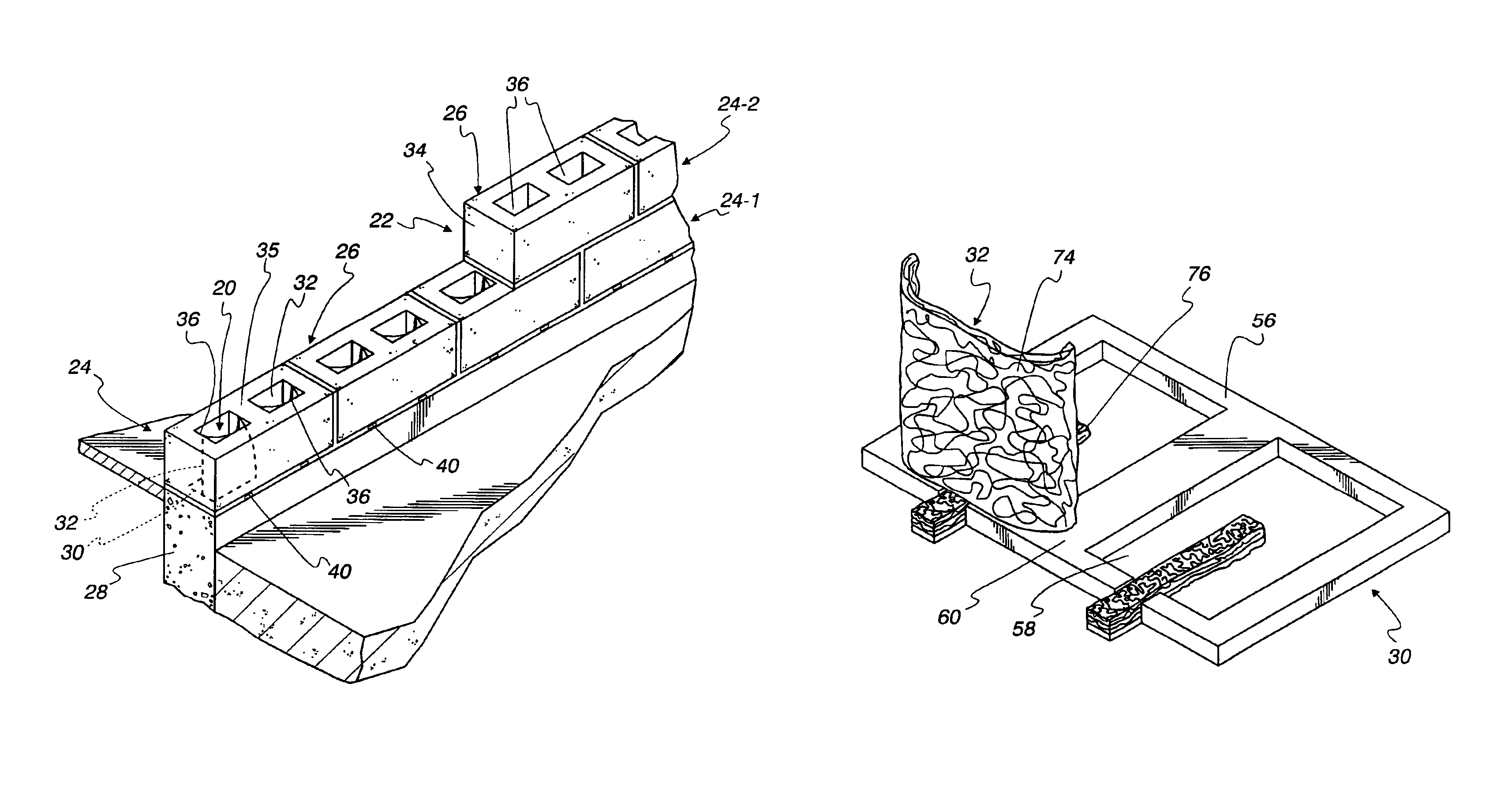
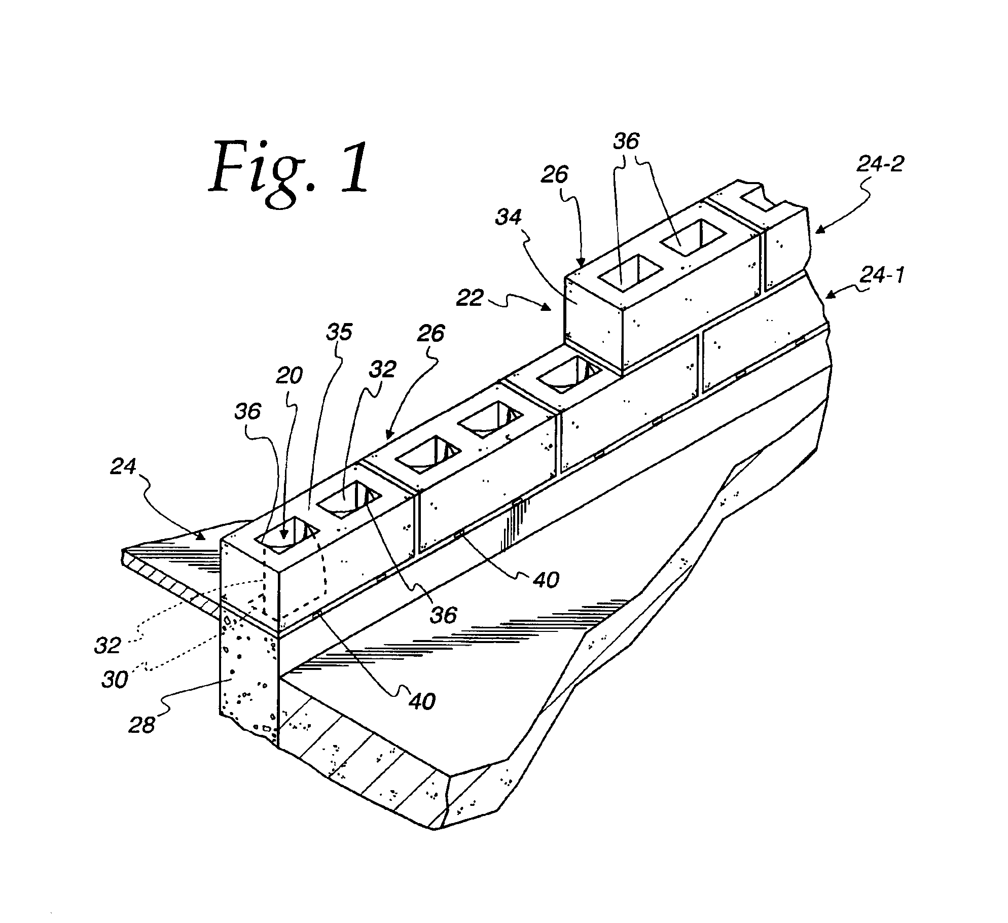
[0038]Referring to FIG. 1, a drainage system 20 is illustrated in connection with concrete masonry unit (CMU) wall construction. In the illustrated embodiment of the invention, the drainage system 20 is used in a single wythe masonry wall construction 22 formed by courses 24 of CMUs 26. The wall construction 22 is used on a building structure including a foundation wall 28. In the illustrated embodiment of the invention, the foundation wall 28 comprises a concrete wall. The foundation wall could be of block construction, as will be apparent to those skilled in the art.

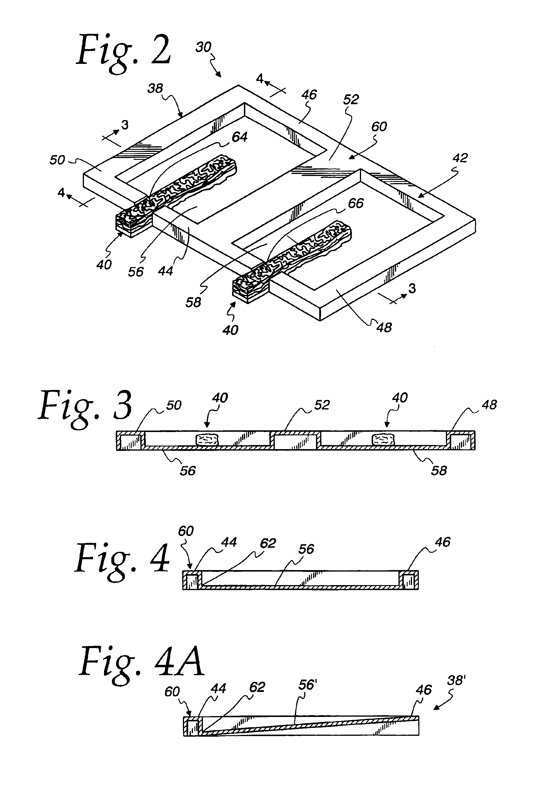
[0039]Referring also to FIG. 10, the drainage system 20 comprises a tray 30 and a pair of blocks 32 of water permeable material.

[0040]CMUs 26 most typically have a nominal height of eight inches, a nominal length of sixteen inches and come in nominal widths of eight, ten or twelve inches. Actual sizes are about ⅜ inches less to allow for a ⅜ inch mortar joint. The CMU 26 comprises a hollow concrete block 34 having a we...


PUM


Abstract

A drainage system for use in concrete masonry unit (CMU) wall construction comprises a tray unit of a size corresponding to size of CMUs, to be received beneath a course of CMUs, in use. The tray unit comprises opposite side flanges to abut a superjacent CMU and supporting a pan therebelow. A strip of water permeable material is attached to an upper surface of the pan and extends transversely beyond a front edge of the pan. A block of water permeable material is positioned above the pan and extends upwardly into a hollow core of a CMU. The water permeable material of the strip and the block has a porosity sufficient to permit water to pass there through but substantially insufficient to permit mortar and debris to pass there through so that water in a hollow core of a CMU drains through the strip.

Description

FIELD OF THE INVENTION[0001]This invention relates to concrete masonry unit wall construction and, more particularly, to a drainage system therefor.BACKGROUND OF THE INVENTION[0002]Single wythe masonry walls are constructed using concrete masonry units (CMUs). CMUs are sometimes referred to as cinder blocks. A CMU consists of a hollow rectangular building block typically having a central web providing two vertical cores or cavities. In singly wythe masonry wall construction a foundation is formed, typically of concrete. The wall is formed by laying the CMUs in alternating fashion in multiple courses depending on the height of the wall. Owing to the construction, the vertical cores of CMUs are aligned to provide a continuous channel from the top of the wall down to the foundation. Mortar is used in joints to join the CMUs.[0003]Cracks in the CMUs can allow water to enter the cores. Moisture can also condense in the cores under changing temperatures. Either way, water may collect in t...

Claims


Application Information

Patent Timeline
Patent Type & Authority Patents(United States)
IPC IPC(8): E04B1/70
CPCE04B1/70E04B1/7053
Inventor SOURLIS, TOM
Owner MORTAR NET OF OHIO LLC
Why Eureka
Try Eureka