
Safety ring binder having sliding actuators

a safety ring and actuator technology, applied in the field of ring binder mechanism, can solve the problems of prior constructions not keeping one from accidentally getting a finger, rings can pinch a finger painfully when they snap shut, etc., and achieve the effect of preventing people from pinching their fingers

Inactive Publication Date: 2005-07-12
HONG KONG STATIONERY MFG
View PDF16 Cites 70 Cited by
  • Summary
  • Abstract
  • Description
  • Claims
  • Application Information

AI Technical Summary

Benefits of technology

[0004]An object of the invention is to prevent people from pinching their fingers between the rings when closing a ring binder mechanism. A related goal is to provide a construction which requires one to use two hands, away from the ring ends, both to close and to open the rings.
[0005]Another object of the invention is to prevent people from opening or closing the ring binder mechanism by manipulating the rings directly, that is, to force the user to use two sliding actuators at the ends of the ring binder mechanism to close and open the rings.

Problems solved by technology

As ring binder users know, the rings can pinch a finger painfully when they snap shut.
Prior constructions do not keep one from accidentally getting a finger between the ring ends when closing the ring binder mechanism.

Method used


Image

  • Safety ring binder having sliding actuators
  • Safety ring binder having sliding actuators
  • Safety ring binder having sliding actuators

Examples


Embodiment Construction

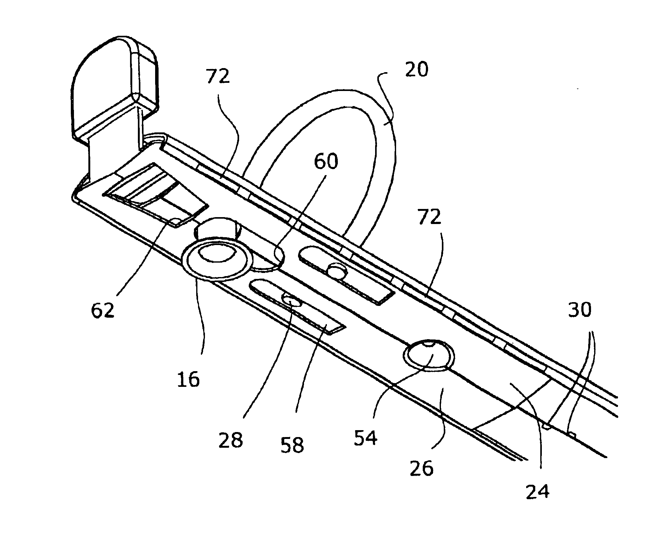
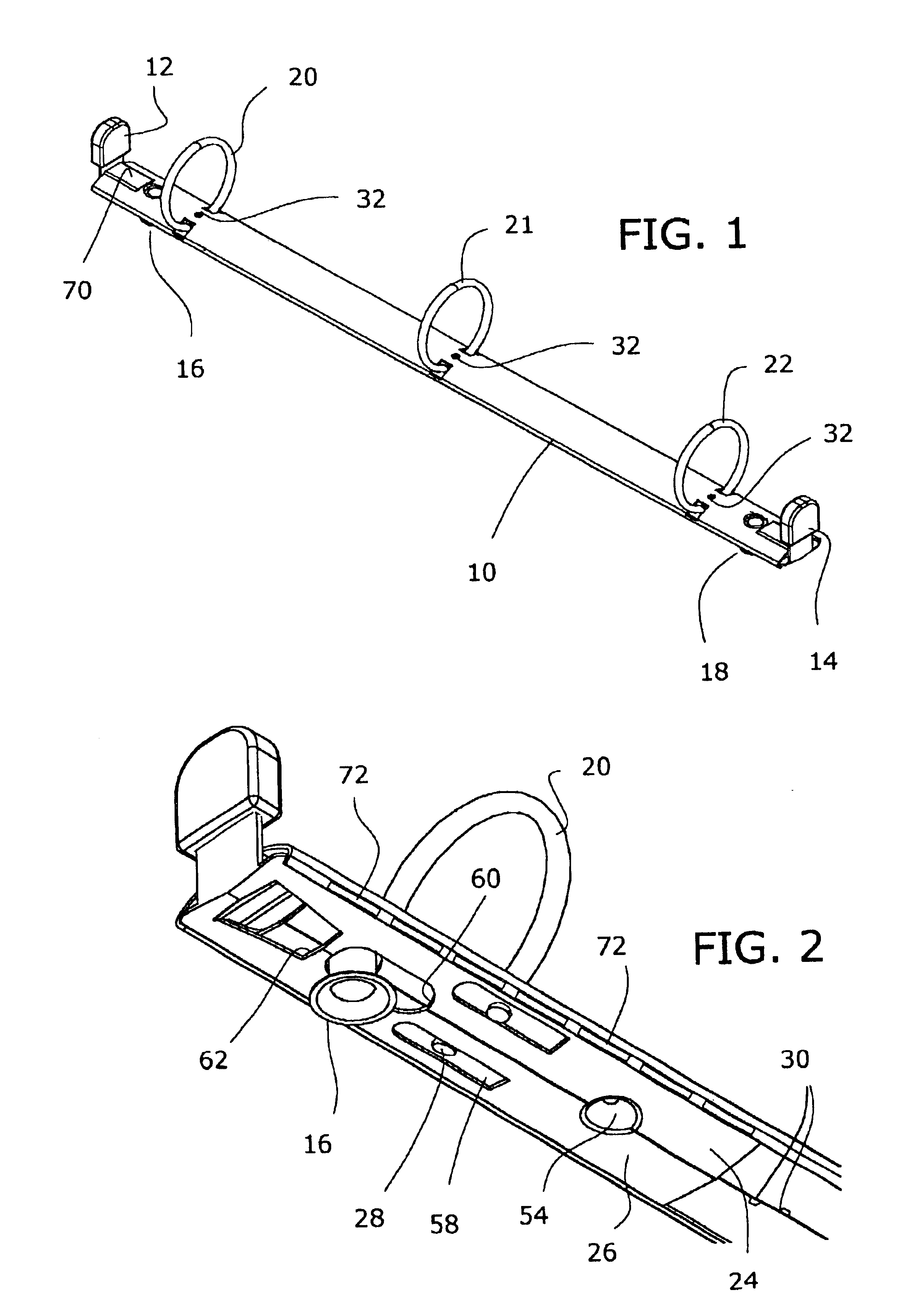
[0014]A ring binder mechanism embodying the invention, illustrated in FIGS. 1 and 2, includes a metal housing 10 which supports opposed sliding actuators 12, 14 at either end. Rivets 16, 18, whose upper ends are secured in holes in the housing, extend downward, for connecting the housing to the spine of a loose leaf ring binder. The rings 20, 21, 22 each comprises two half-rings which are secured to the respective blades 24, 26, by crimping, swaging or staking the lower ends 28 of the rings, where they protrude through holes in the blades.

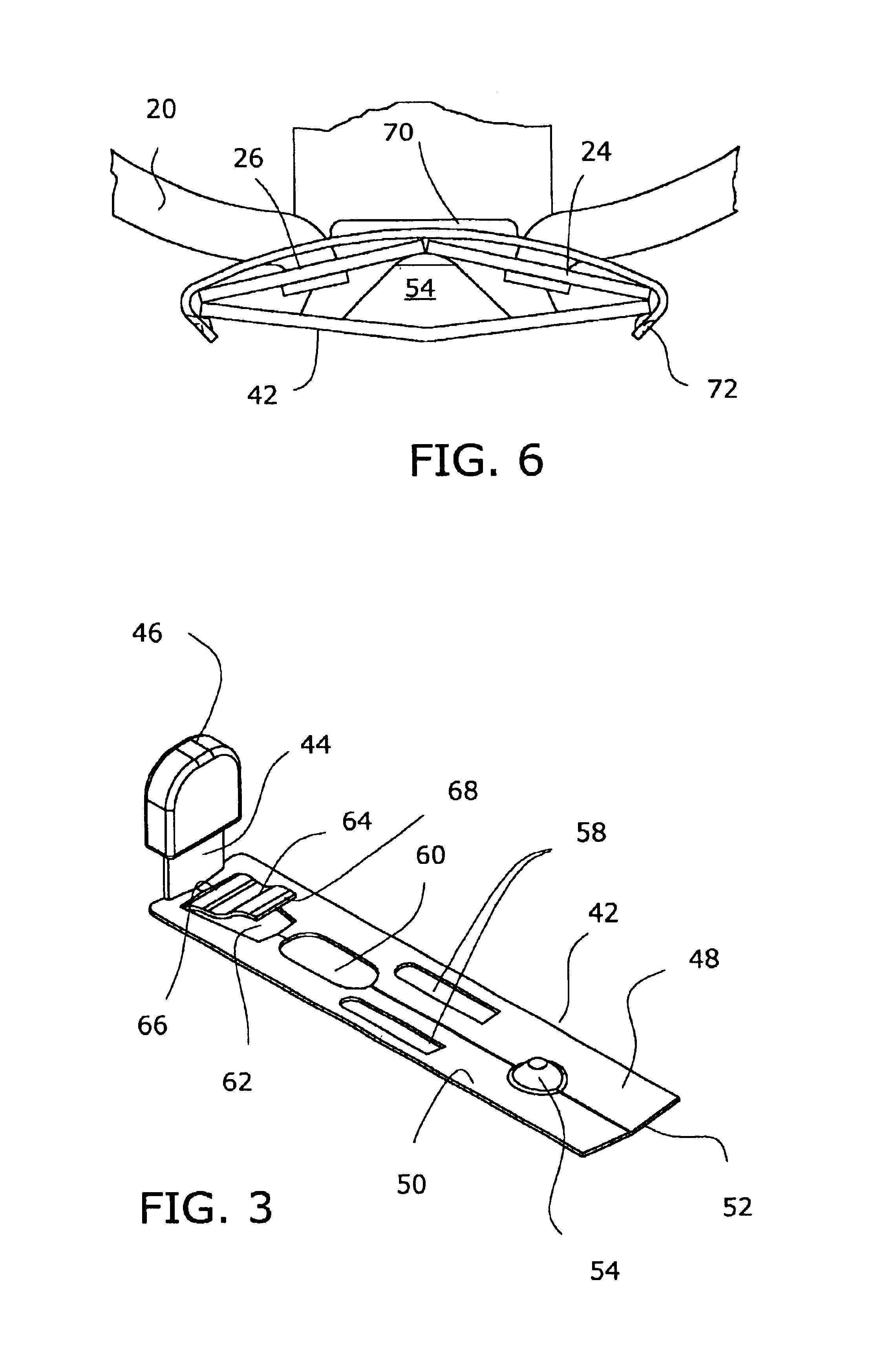
[0015]In FIG. 2, one can see the two blades 24, 26, their inner edges abutting, and being retained in alignment by alternating tab-like deformations 30 formed along the inner edges. In FIGS. 1, 2 and 4, the rings are closed, the inner edges of the blades being below an imaginary plane containing the outer edges of the blades. When the rings are opened (FIGS. 5 and 6), the inner edges move above that plane. The extreme of upward movement is determin...


PUM


Abstract

A safety ring binder mechanism helps prevent finger pinching by requiring simultaneous opposite movement of sliding actuators at both ends of the mechanism in order to open and close the rings. When the actuators are outermost, dimples on the actuators press the blades of the device against the housing, holding the rings open. When the actuators are pushed in, inclined tongues cam the ends of the blades downward, forcing the rings to close and holding them in a closed position.

Description

BACKGROUND OF THE INVENTION[0001]This invention relates to a ring binder mechanism for securing loose-leaf papers.[0002]A typical ring binder mechanism has a sheet metal housing which is longitudinally stiff, but laterally flexible, and contains a pair of blades which are hinged along mating edges. Each blade supports a number of ring halves. The blades have a combined width slightly greater than the width of the housing, so that they toggle between two extreme positions, in one of which the tips of the ring halves meet, forming closed rings, and in another of which the ring halves are open, allowing one to insert or remove loose-leaf papers.[0003]As ring binder users know, the rings can pinch a finger painfully when they snap shut. Prior constructions do not keep one from accidentally getting a finger between the ring ends when closing the ring binder mechanism.SUMMARY OF THE INVENTION[0004]An object of the invention is to prevent people from pinching their fingers between the ring...

Claims


Application Information

Patent Timeline
Patent Type & Authority Patents(United States)
IPC IPC(8): B42F13/26B42F13/00
CPCB42F13/26
Inventor WONG, YIU WING
Owner HONG KONG STATIONERY MFG
Learn More