
Headlamp adjuster

a technology of headlamps and adjusters, which is applied in the direction of fixed installations, lighting and heating devices, instruments, etc., can solve the problems of not being adequately illuminated soon, objects might not be illuminated, and the area in front of the vehicle may not be properly illuminated for adequate recognition of something in front of the vehicl

Inactive Publication Date: 2005-07-19
ASYST TECH LP
View PDF6 Cites 13 Cited by
  • Summary
  • Abstract
  • Description
  • Claims
  • Application Information

AI Technical Summary

Benefits of technology

The solution significantly reduces labor requirements for headlamp installation, allows for rapid and secure adjustment, and offers flexibility in tool usage, while being cost-effective and easy to manufacture.

Problems solved by technology

If the headlamp is not properly adjusted vertically, the headlamp may focus the light too close to the vehicle, not adequately lighting the distance.
If the field of light is too short, objects might not be illuminated soon enough for a driver to react to the presence of the object, even if the vehicle is being operated within legal speed limits.
Conversely, if the headlamp is aimed to focus too far in the distance, the area in front of the vehicle may not be properly illuminated for adequate recognition of something in front of the vehicle.
Further, a headlamp aimed too distant may “blind” an oncoming driver even in the dimmed or “low-beam” condition.
If the headlamp is aimed to direct the beam of light too far to the left, oncoming drivers can be blinded.
If focused too far to the right, the primary field directly in front of the automobile may not be properly illuminated.
Improperly directed headlamps can be distracting and unsafe.
Although adjusters of this type have proven to be useful, because of the many individual components required, labor requirements for assembly and installation are high.

Method used


Image

  • Headlamp adjuster
  • Headlamp adjuster
  • Headlamp adjuster

Examples


Embodiment Construction

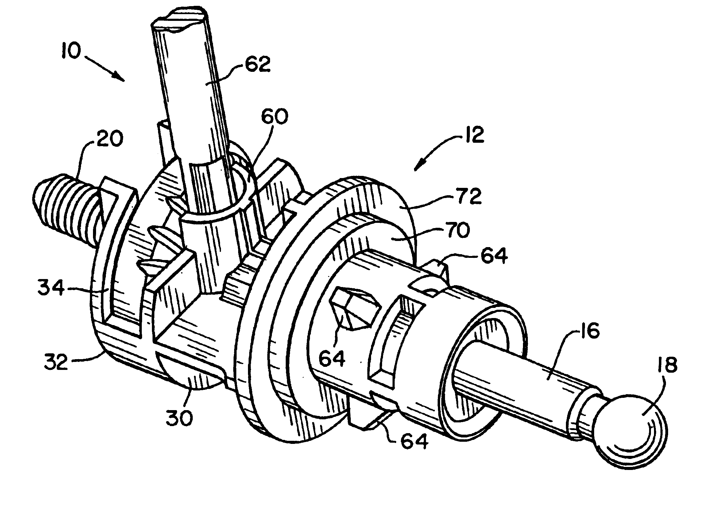
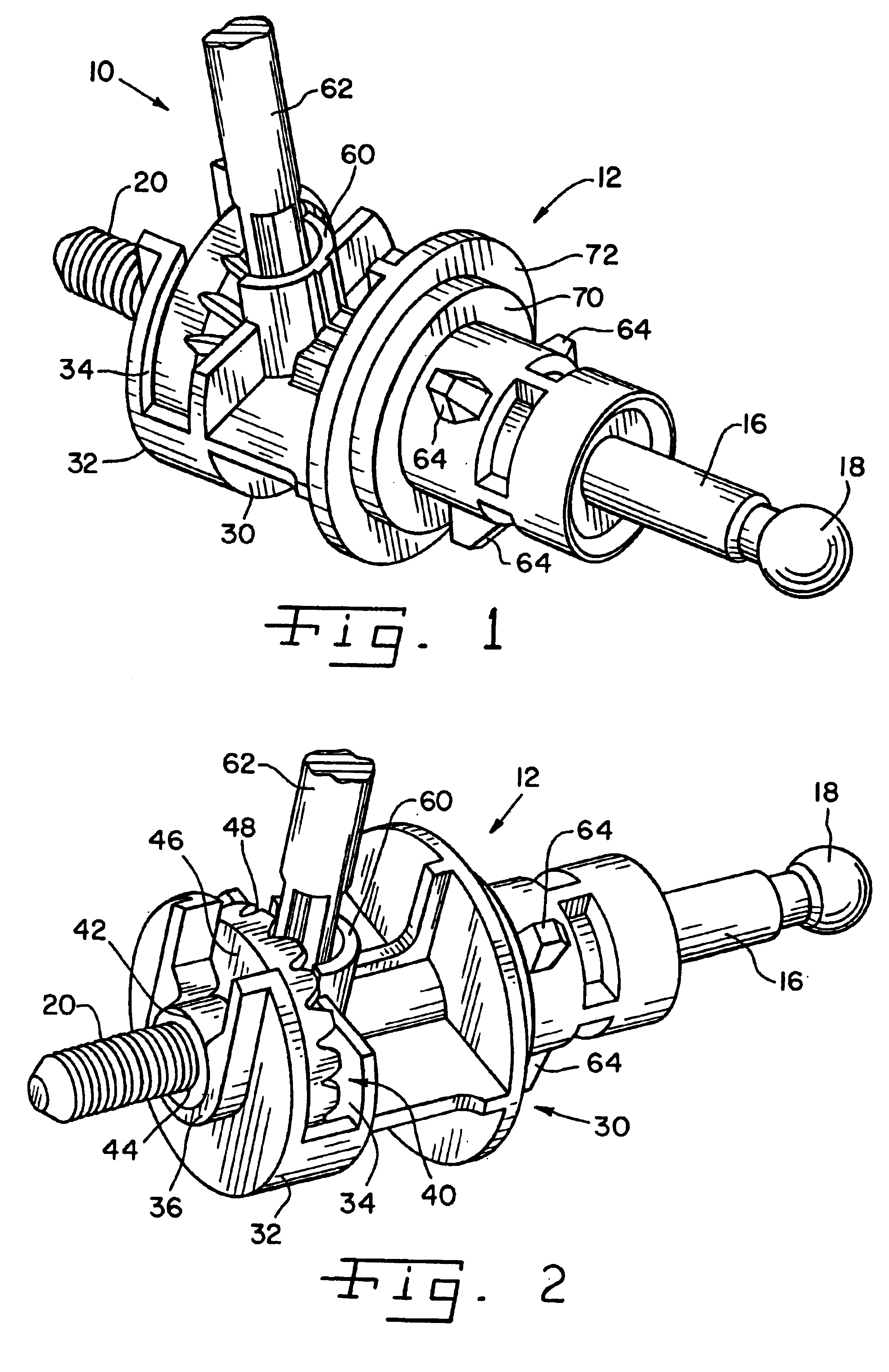
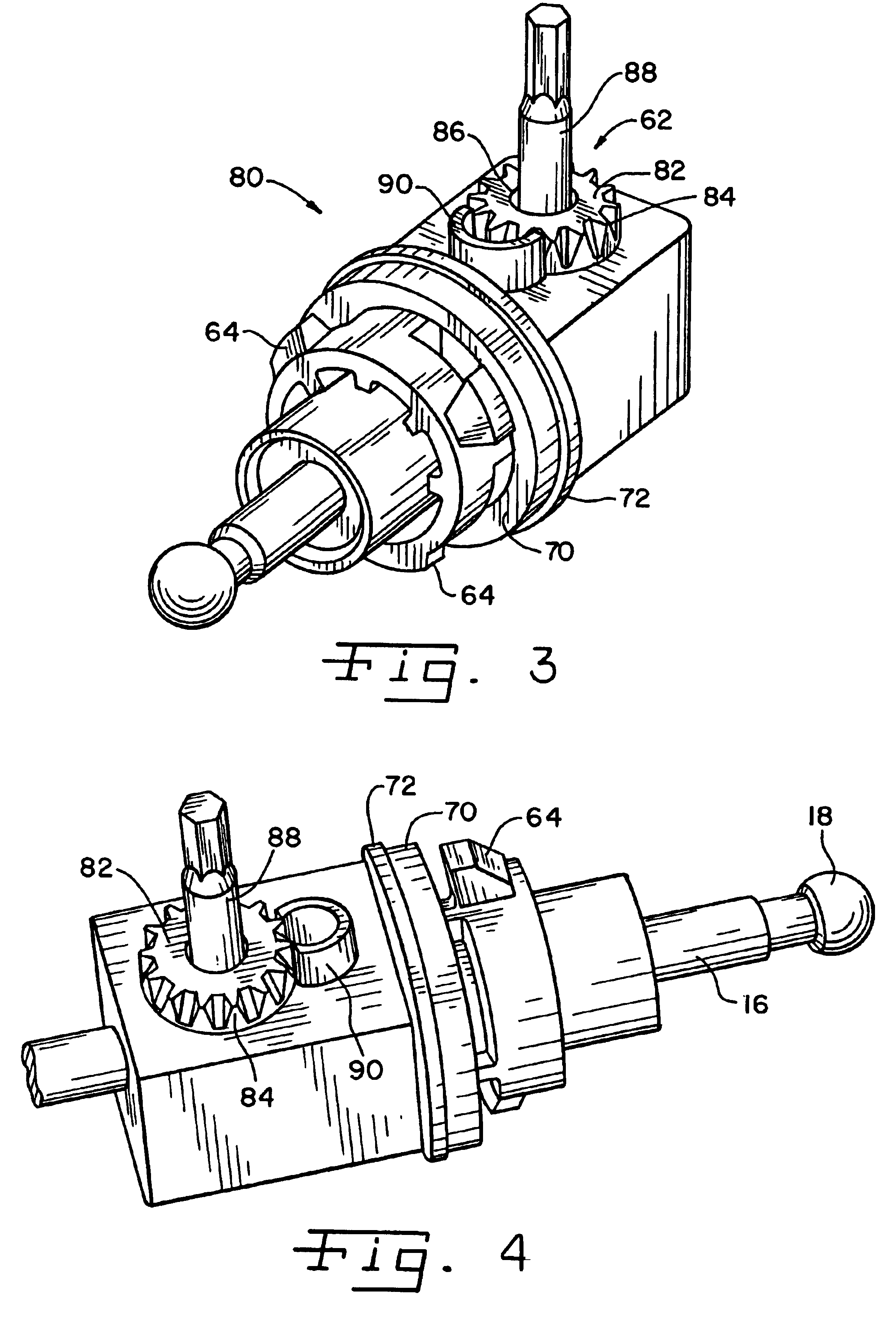
[0022]Referring now and more specifically to the drawings and to FIG. 1 in particular, numeral 10 designates a headlamp adjuster assembly which includes headlamp adjuster 12 and headlamp panel 14 (FIG. 6) in accordance with the present invention. Advantageously, headlamp adjuster 12 can be made of plastic or, alternatively, of other non-corrosive materials such as zinc, stainless steel or the like. As a further alternative, inexpensive metals also can be used for some or all of the components to be described hereinafter. Headlamp adjuster 12 is secured in panel 14 as will be described subsequently herein.

[0023]Headlamp adjuster 12 includes a shaft 16 adapted for operatively engaging a headlamp reflector (not shown). Those skilled in the art will readily recognize and understand how such operative connection can be made using a bulbous end 18 of shaft 16 secured in a cup (not shown) of the reflector (not shown). The reflector (not shown) is connected to the vehicle about pivot points...


PUM


Abstract

A headlamp adjuster and a headlamp adjustment assembly having a housing, a shaft axially moveable in the housing and a gear having a thread engaging a thread of the shaft for causing axial movement of the shaft from rotation of the gear. The gear and / or housing are adapted to receive rotary input tools for adjustment. All parts can be made of plastic or other non-corrosive materials.

Description

CROSS-REFERENCE TO RELATED APPLICATIONS[0001]This Non-Provisional Application claims benefit to U.S. Provisional Application Ser. No. 60 / 394,126, filed Jul. 3, 2002.FIELD OF THE INVENTION[0002]The present invention relates to right angle adjustment mechanisms and, more particularly, the invention relates to adjuster mechanisms useful for adjusting the aim of headlights found in various motor vehicles.BACKGROUND OF THE INVENTION[0003]Headlamps on motor vehicles require proper aiming, both vertically and horizontally, for safe and optimal performance. From time-to-time, it is necessary to readjust the aim of vehicle headlamps. If the headlamp is not properly adjusted vertically, the headlamp may focus the light too close to the vehicle, not adequately lighting the distance. If the field of light is too short, objects might not be illuminated soon enough for a driver to react to the presence of the object, even if the vehicle is being operated within legal speed limits. Conversely, if ...

Claims


Application Information

Patent Timeline
Patent Type & Authority Patents(United States)
IPC IPC(8): G01B5/24F21W101/10B60Q1/076
CPCB60Q1/076
Inventor GATTONE, MICHAEL T.GALINSKI, ADOLPH G.
Owner ASYST TECH LP
Learn More