Variable inclination continuous transverse stub array

a transverse stub array and variable inclination technology, applied in the direction of leaky waveguide antennas, partial array feeding systems, antenna adaptation in movable bodies, etc., can solve the problems of recurring (component, assembly, test, etc.) cost, prime power and cooling requirements associated with such electronically controlled phased arrays can be prohibitive in many applications, and conventional arrays can suffer from degraded ohmic efficiency (peak gain, poor scan efficiency)

Inactive Publication Date: 2005-07-19
RAYTHEON CO
View PDF8 Cites 28 Cited by
  • Summary
  • Abstract
  • Description
  • Claims
  • Application Information

AI Technical Summary

Problems solved by technology

The recurring (component, assembly, and test) costs, prime power, and cooling requirements associated with such electronically controlled phased arrays can be prohibitive in many applications.
In addition, such conventional arrays can suffer from degraded ohmic efficiency (peak gain), poor scan efficiency (gain roll-off with scan), limited instantaneous bandwidth (data rates), and data stream discontinuities (signal blanking between commanded scan positions).
These cost and performance issues can be particularly pronounced for physically large and / or high-frequency arrays where the overall phase-shift / transmit-receive module count can exceed many tens of thousands elements.

Method used


Image

  • Variable inclination continuous transverse stub array
  • Variable inclination continuous transverse stub array
  • Variable inclination continuous transverse stub array

Examples


Embodiment Construction

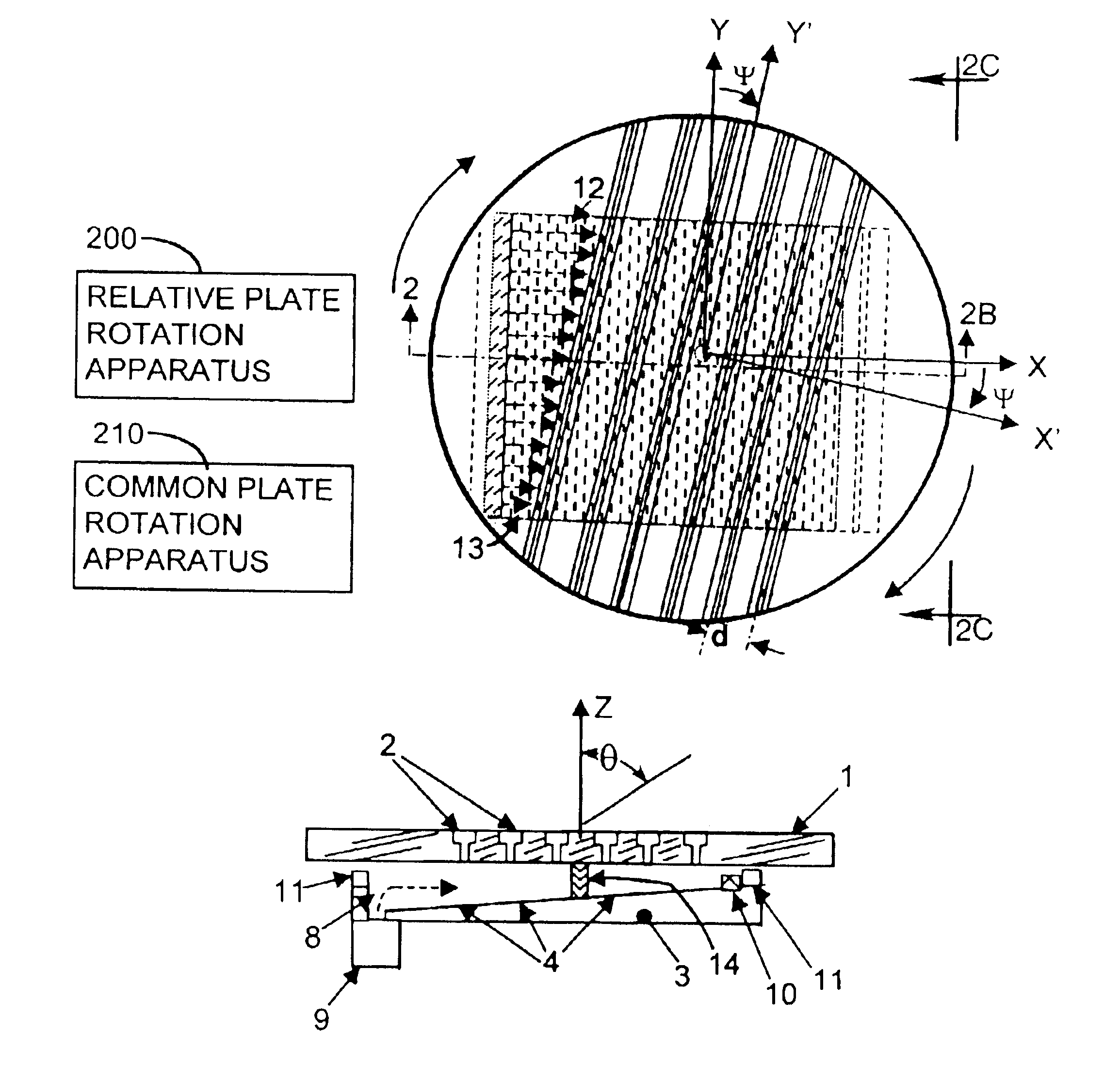
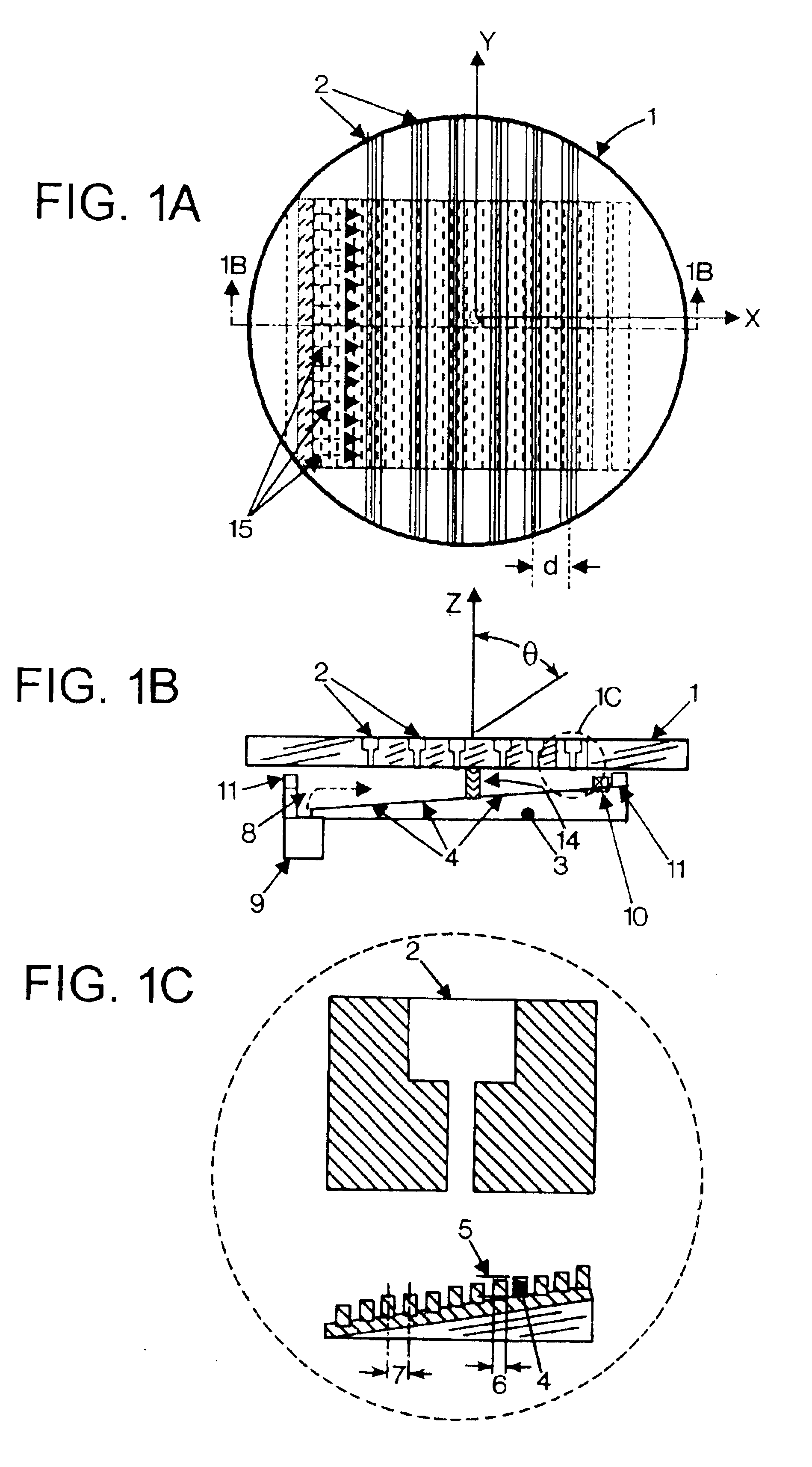
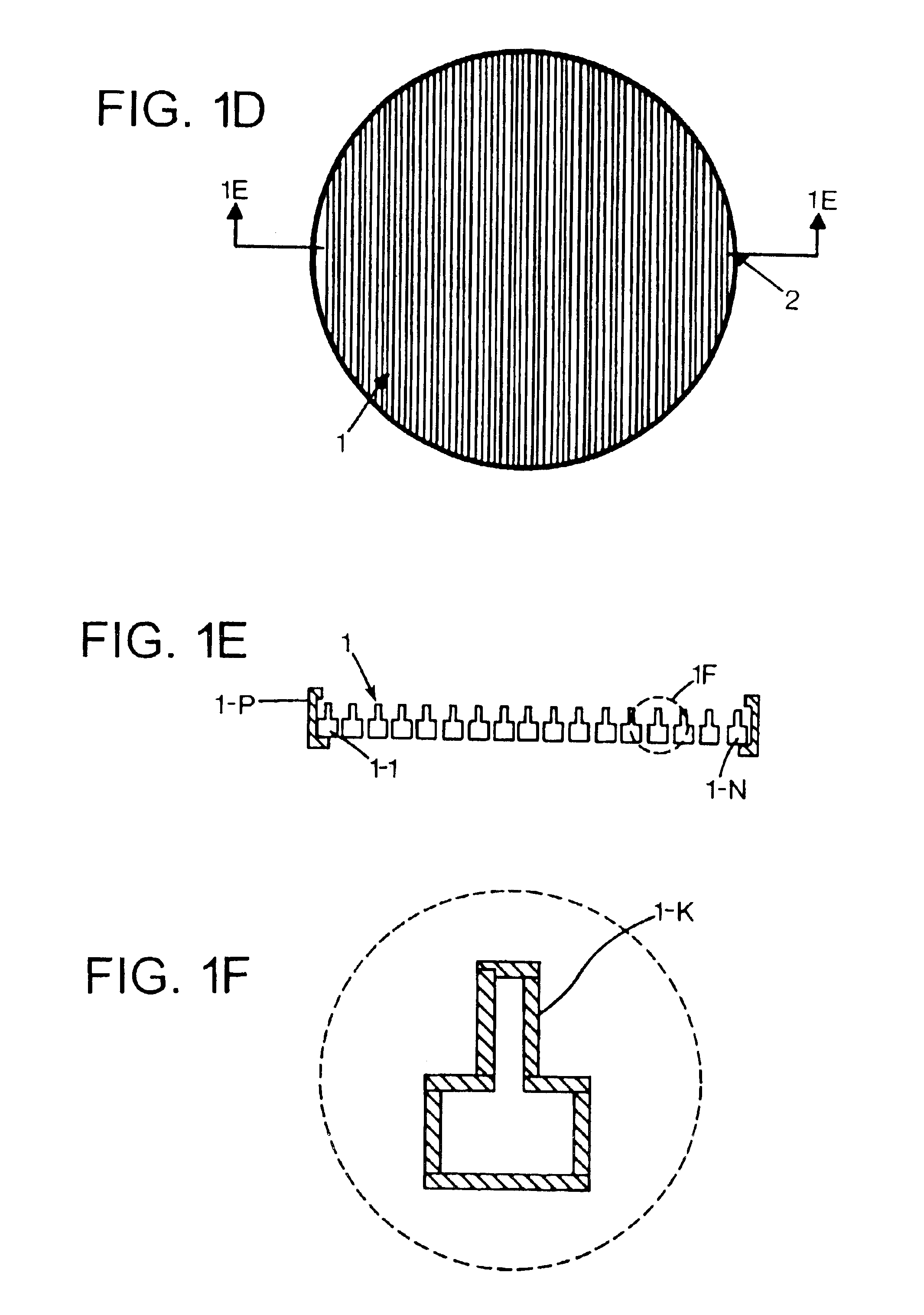
[0039]A Variable Inclination Continuous Transverse Stub (VICTS) array in an exemplary embodiment includes two plates, one (upper) comprising a one-dimensional lattice of continuous radiating stubs and the second (lower) comprising one or more line sources emanating into the parallel-plate region formed and bounded between the upper and lower plates. Mechanical rotation of the upper plate relative to the lower plate serves to vary the inclination of incident parallel-plate modes, launched at the line source(s), relative to the continuous transverse stubs in the upper plate, and in doing so constructively excites a radiated planar phase-front whose angle relative to the mechanical normal of the array (theta) is a simple continuous function of the relative angle (ψ) of (differential) mechanical rotation between the two plates. Common rotation of the two plates in unison moves the phase-front in the orthogonal azimuth (phi) direction. Exemplary embodiments of this simple innovative scan...


PUM


Abstract

An antenna array employing continuous transverse stubs as radiating elements is disclosed. In an exemplary embodiment, the array includes an upper conductive plate structure comprising a set of continuous transverse stubs, and a lower conductive plate structure disposed in a spaced relationship relative to the upper plate structure. A rotation apparatus provides rotation between the upper plate structure and the lower plate structure.

Description

BACKGROUND OF THE DISCLOSURE[0001]Many antenna applications require directive (high-gain, narrow beamwidth) beams which can be selectively steered over a pseudo-hemispherical scan volume while maintaining a conformal (thin) mechanical profile. Such low-profile two-dimensionally scanned antennas are generically referred to as phased arrays in that the angle between the electromagnetic phase-front and the mechanical normal of the array can be selectively varied in two-dimensions. Conventional phased arrays include a fully-populated lattice of discrete phase-shifters or transmit-receive elements each requiring their own phase- and / or power-control lines. The recurring (component, assembly, and test) costs, prime power, and cooling requirements associated with such electronically controlled phased arrays can be prohibitive in many applications. In addition, such conventional arrays can suffer from degraded ohmic efficiency (peak gain), poor scan efficiency (gain roll-off with scan), lim...

Claims


Application Information

Patent Timeline
Patent Type & Authority Patents(United States)
IPC IPC(8): H01Q13/10H01Q1/27H01Q9/00H01Q1/32H01Q1/34H01Q3/04H01Q13/20H01Q21/00
CPCH01Q3/04H01Q13/20H01Q21/0031H01Q3/14H01Q13/28H01Q15/24
Inventor MILROY, WILLIAM W.COPPEDGE, STUART B.LEMONS, ALAN C.
Owner RAYTHEON CO
Why Eureka
Try Eureka