Heat exchanger

a heat exchanger and heat exchanger technology, applied in indirect heat exchangers, lighting and heating apparatuses, laminated elements, etc., can solve the problems of relatively expensive construction and lack of flexibility

Inactive Publication Date: 2005-07-26
MODINE MFG CO
View PDF20 Cites 76 Cited by
  • Summary
  • Abstract
  • Description
  • Claims
  • Application Information

AI Technical Summary

Benefits of technology

[0004]It is the principal object of the invention to provide a new and improved heat exchanger that may utilized in many heat exchang...

Problems solved by technology

While such heat exchangers work well for their intended function, heretofore, they have been constructed i...

Method used


Image

  • Heat exchanger
  • Heat exchanger
  • Heat exchanger

Examples


Embodiment Construction

[0027]The heat exchanger forming the invention hereof will described as a heat exchanger intended for use in an exhaust gas recirculation system for an internal combustion engine. However, those skilled in the art will recognize that it is susceptible to other uses as well and no limitation is intended to its use solely as an exhaust gas heat exchanger except as expressly stated in the appended claims. For example, the invention is susceptible to use wherever heat exchange between two fluids is required as, for example, as a liquid / gas heat exchanger.

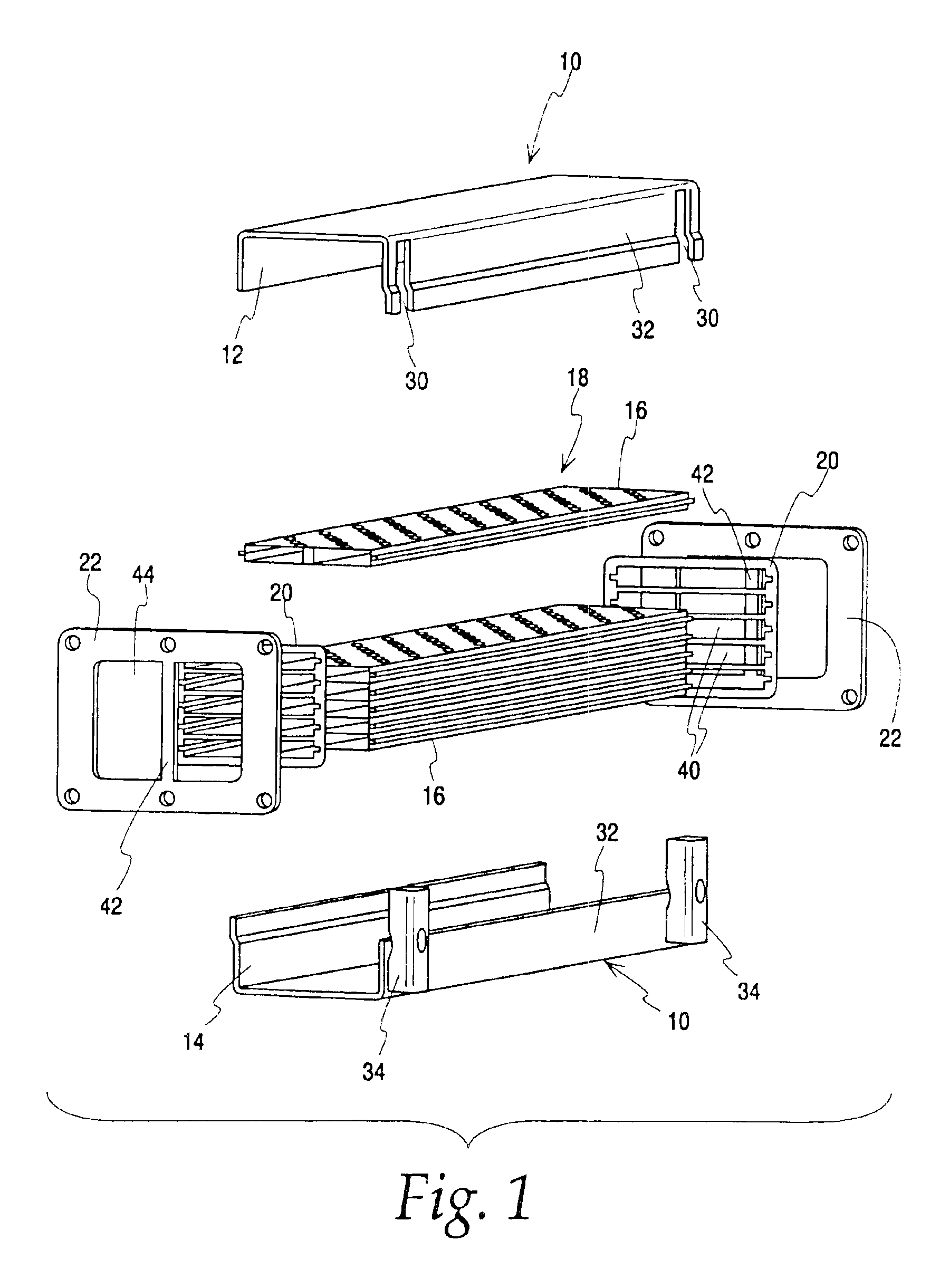
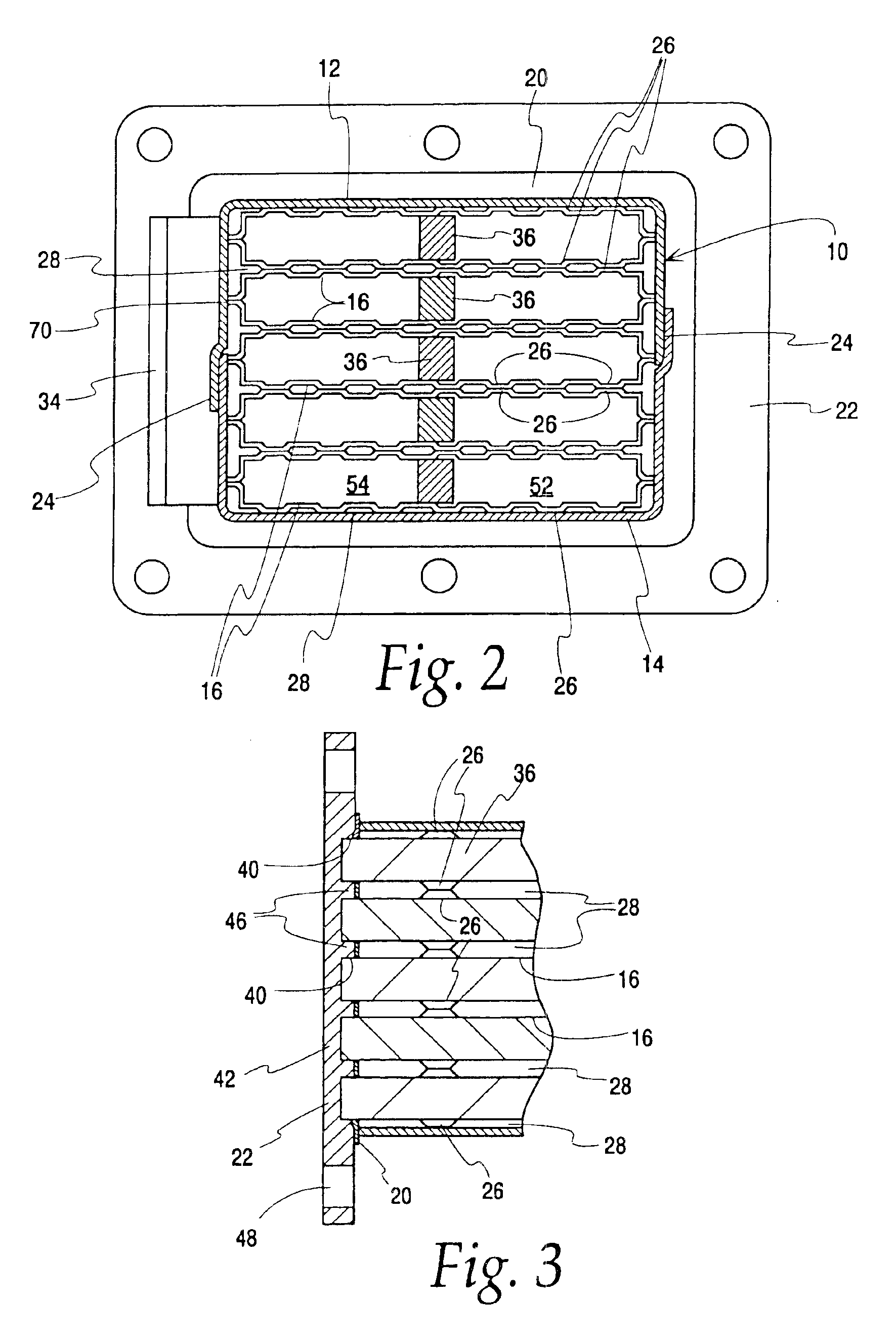
[0028]Referring now to the drawings, and FIG. 1 in particular, an exemplary embodiment of a heat exchanger made according to the invention is illustrated therein and is seen to include a housing, generally designated 10, made up of a top half 12 and a bottom half 14 which are substantially identical to each other.

[0029]Contained within the housing is a plurality of elongated, flat, tubes 16, arranged in a stack, generally designated 18....


PUM


Abstract

An economically manufactured heat exchanger is provided and includes a plurality of elongated, straight, flat tubes (16), each formed of two identical halves (78,80) joined to each other in mirror image fashion and each having opposed open ends and all arranged in a stack (18). At least one spacer wall (36) is disposed within each tube and extends generally from end to end thereof to define at least two side-by-side first fluid flow paths within a tube. An elongated housing (10) contains the stack and includes spaced headers (20,22) with each header including a tube slot for the adjacent end of each tube (16) in the stack (18). Spacers (26) in the stack separate adjacent tubes in the stack from one another and the spacers include ribs defining a serpentine flow path for a second fluid. An opening (30) is located in the housing (10) near each end thereof and is in fluid communication with the second fluid flow path (28).

Description

FIELD OF THE INVENTION[0001]This invention relates to heat exchangers generally, and more specifically, to an exhaust gas heat exchanger for use in exhaust recirculation systems for internal combustion engines.BACKGROUND OF THE INVENTION[0002]Heat exchangers useable in exhaust gas recirculation systems used with internal combustion engines, typically in vehicles, are known. One such heat exchanger is shown, for example, in German Patent Publication DE 101 24 383. While such heat exchangers work well for their intended function, heretofore, they have been constructed in a relatively expensive design that may lack flexibility, particularly where two exhaust channels are required.[0003]The present invention is directed to providing a heat exchanger, and more particularly, the heat exchanger that may be utilized in an exhaust recirculation system that is economically fabricated and which can be readily utilized as a single channel or a multiple channel exhaust gas heat exchanger.SUMMARY...

Claims


Application Information

Patent Timeline
IPC IPC(8): F28F3/00F28F3/04F28D9/00F28D7/16
CPCF28D7/1684F28D9/0037F28F9/001F28F3/044F28D21/0003F28F2240/00F28F2250/104
Inventor KNECHT, WOLFGANGSTRAHLE, ROLANDSOLDNER, JORGGUHRING, WALTERKAISSLING, RAINERSCHATZ, HARALDSTOLZ, ANDREAS
Owner MODINE MFG CO
Why Eureka
Try Eureka