Vehicle compartment radio LAN system

a radio lan and vehicle compartment technology, applied in active radio relay systems, wireless communication, transportation and packaging, etc., can solve the problems of inability to carry out radio communication continuously between the terminal and the repeater, and inability to carry out radio communication between the terminals in each seat row

Inactive Publication Date: 2005-07-26
YAZAKI CORP
View PDF20 Cites 7 Cited by
  • Summary
  • Abstract
  • Description
  • Claims
  • Application Information

AI Technical Summary

Benefits of technology

[0010]Accordingly, the present invention has been achieved in views of the above described problems and therefore, an object of the invention is to provide a vehicle compartment radio LAN system allowing communication between ter...

Problems solved by technology

As a result, a terminal brought into a second seat or third seat cannot communicate with the terminal in front of the front seat, which is a conventional problem to be solved.
Further, there is another problem that radio communication cannot be carried out between terminals in each seat row, such as in the gap between the...

Method used


Image

  • Vehicle compartment radio LAN system
  • Vehicle compartment radio LAN system
  • Vehicle compartment radio LAN system

Examples


first embodiment

[0031]Hereinafter, an example of installation of the repeater according to the vehicle compartment radio LAN system of the first embodiment will be described with reference to the accompanying drawings.

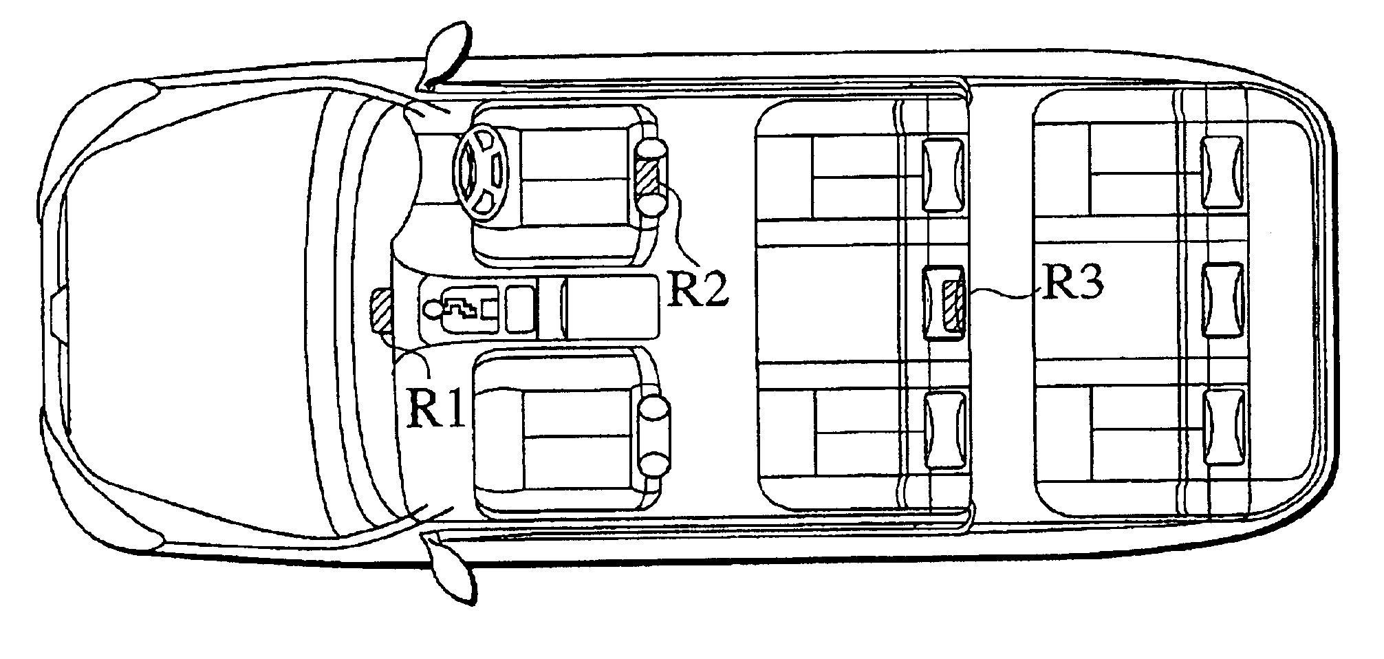
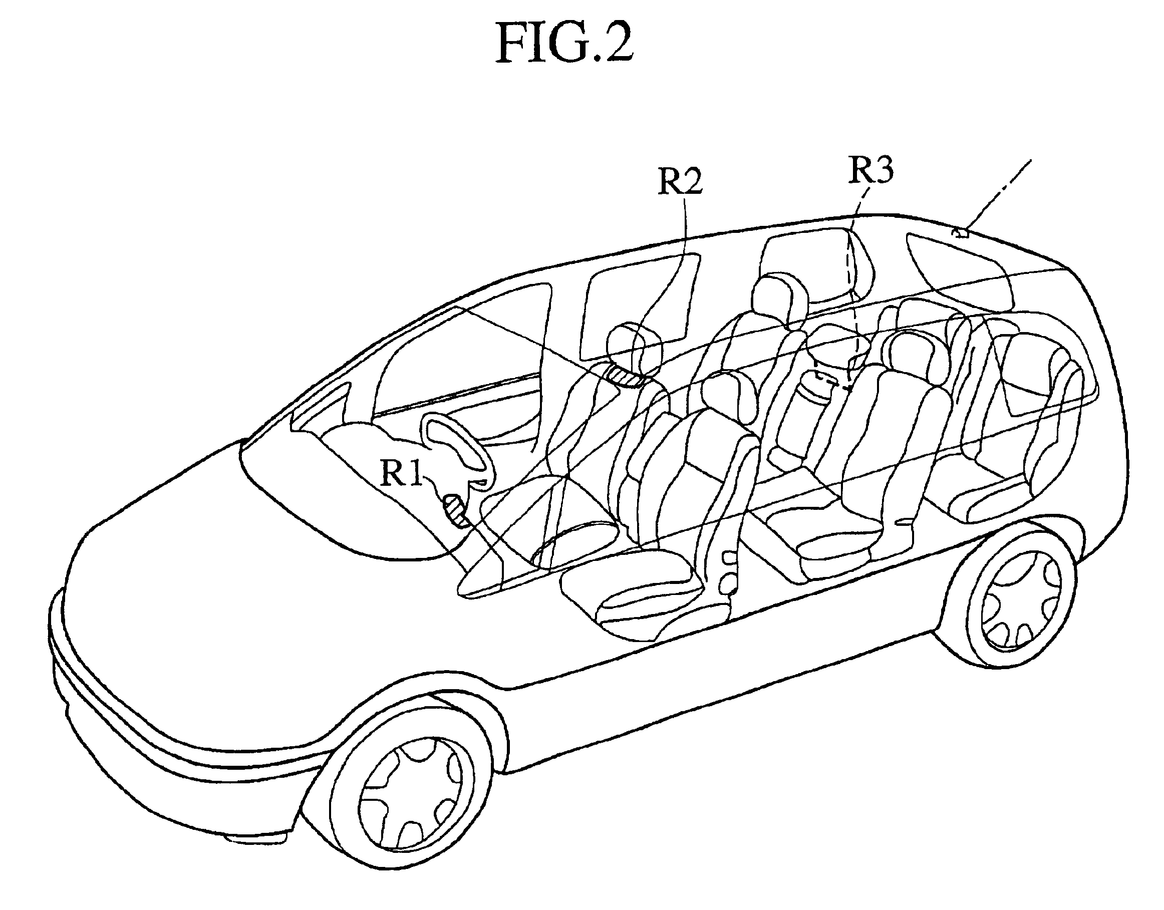
[0032]FIG. 2 is a perspective view showing a first installation example. FIGS. 3A, 3B are a side view and a plan view of the first installation example. As shown in FIG. 2 and FIGS. 3A, 3B, a repeater R1 is mounted on a dash board in front of the front seat. A repeater R2 is mounted on the back of the front seat (the driver's seat in FIG. 2) just in front of a second seat and a repeater R3 is mounted on the back of the second seat just in front of a third seat.

[0033]Therefore, as shown in FIG. 4, a terminal installed in the front seat is capable of communicating with the repeater R1 and a terminal installed in the second seat is capable of communicating with the repeater R2. Further, a terminal installed in the third seat is capable of communicating with the repeater R3.

[0034]FIG. 5 i...

second embodiment

[0044]Next, a vehicle compartment radio LAN system of a second embodiment will be described with reference to FIG. 8.

[0045]As shown in FIG. 8, the vehicle compartment radio LAN system 1 of this embodiment is comprised of plural repeaters R1, R2, R3, which communicate by radio with plural terminals (N1, . . . N7) installed in or brought into the vehicle compartment.

[0046]The vehicle compartment radio LAN system 1 shown in FIG. 8 is indicated about a case where the three repeaters R1, R2, R3 are provided. These repeaters R1, R2, R3 cover all region having a possibility that any terminal may exist and are installed at each position having a lowest possibility that electronic wave sent from the terminal may be interrupted. Further, it is assumed that the repeaters R1, R2, R3 are mounted in such a manner capable of communicating securely irrespective of radio communication or wired communication and the repeater R1 is connected to the wired LAN 2.

[0047]The vehicle compartment radio LAN s...


PUM


Abstract

This invention provides a vehicle compartment radio LAN system for communicating with a terminal installed in a vehicle compartment through a repeater, wherein a repeater is provided in front of each seat row. Thus, a terminal installed in a front seat communicates by radio through a repeater, a terminal installed in a second seat communicates by radio through another repeater and a terminal installed in a third seat communicates by radio through still another repeater.

Description

CROSS REFERENCE TO RELATED APPLICATION[0001]This application claims benefit of priority under 35 U.S.C. § 119 to Japanese Patent Application No.2000-35589, filed on Feb. 14, 2000, the entire contents of which are incorporated by reference herein.BACKGROUND OF THE INVENTION[0002]1. Field of the Invention[0003]The present invention relates to a vehicle compartment radio LAN system and more particularly to a vehicle compartment radio LAN system which enables communication between terminals provided on different seat rows by providing each seat row with a repeater.[0004]2. Description of the Related Art[0005]In a conventional vehicle compartment radio LAN system, a radio terminal is mounted in front of a front seat such as dash board so as to communicate with another terminal installed in a front seat by radio.[0006]In a conventional radio LAN system in office room or the like, as shown in FIG. 1, repeaters 102a, 102b, 102c connected to a wired LAN 101 are mounted on the ceiling, so tha...

Claims


Application Information

Patent Timeline
IPC IPC(8): H04L12/28B60R16/02
CPCH04B7/155H04B7/18506H04W16/26H04W84/12
Inventor NAKATSUGAWA, YOSHINORI
Owner YAZAKI CORP
Why Eureka
Try Eureka