Power supply control device, method for controlling power supply, program and power supply device

a power supply and control device technology, applied in process and machine control, safety/protection circuits, instruments, etc., can solve problems such as failure to confirm the overload the condition of the power supply device, and the type of state that does not satisfy the user

Inactive Publication Date: 2013-02-05
TDK LAMBDA CORP +1
View PDF7 Cites 607 Cited by
  • Summary
  • Abstract
  • Description
  • Claims
  • Application Information

AI Technical Summary

Benefits of technology

[0010]According to the first aspect of the invention, it is provided a power supply control device comprising: a short circuit detecting part that determines a short circuit condition of an output side by measuring voltage of a circuit connected in parallel to the output side and having a diode; and a constant current supplying part that supplies constant current in a forward bias direction of the diode of the circuit connected in parallel to the output side and having the diode, wherein the short circuit detecting part determines that the short circuit condition of the output side is eliminated when the voltage of the circuit connected in parallel to the output side and having the diode, that receives the supplied constant current from the constant current supplying part, greater than or equal to a predetermined threshold value.
[0014]According to the present invention, the power supply can be restarted immediately after the overload condition of the power supply device is eliminated.

Problems solved by technology

Note that a general cause of an overload condition of the power supply device is when a load is short-circuited.
Therefore, confirmation of the overload condition of the power supply device cannot be performed until the occurrence of the periodic time that is set by the timer.
This type of state does not satisfy a user who desires to restart the power supply as soon as possible.

Method used


Image

  • Power supply control device, method for controlling power supply, program and power supply device
  • Power supply control device, method for controlling power supply, program and power supply device
  • Power supply control device, method for controlling power supply, program and power supply device

Examples


embodiments using ic

and Program

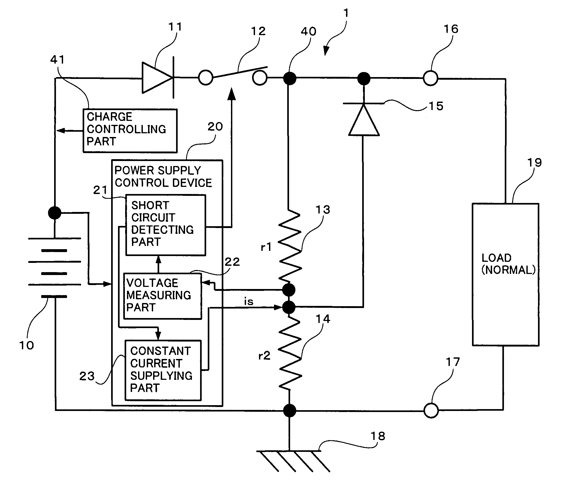
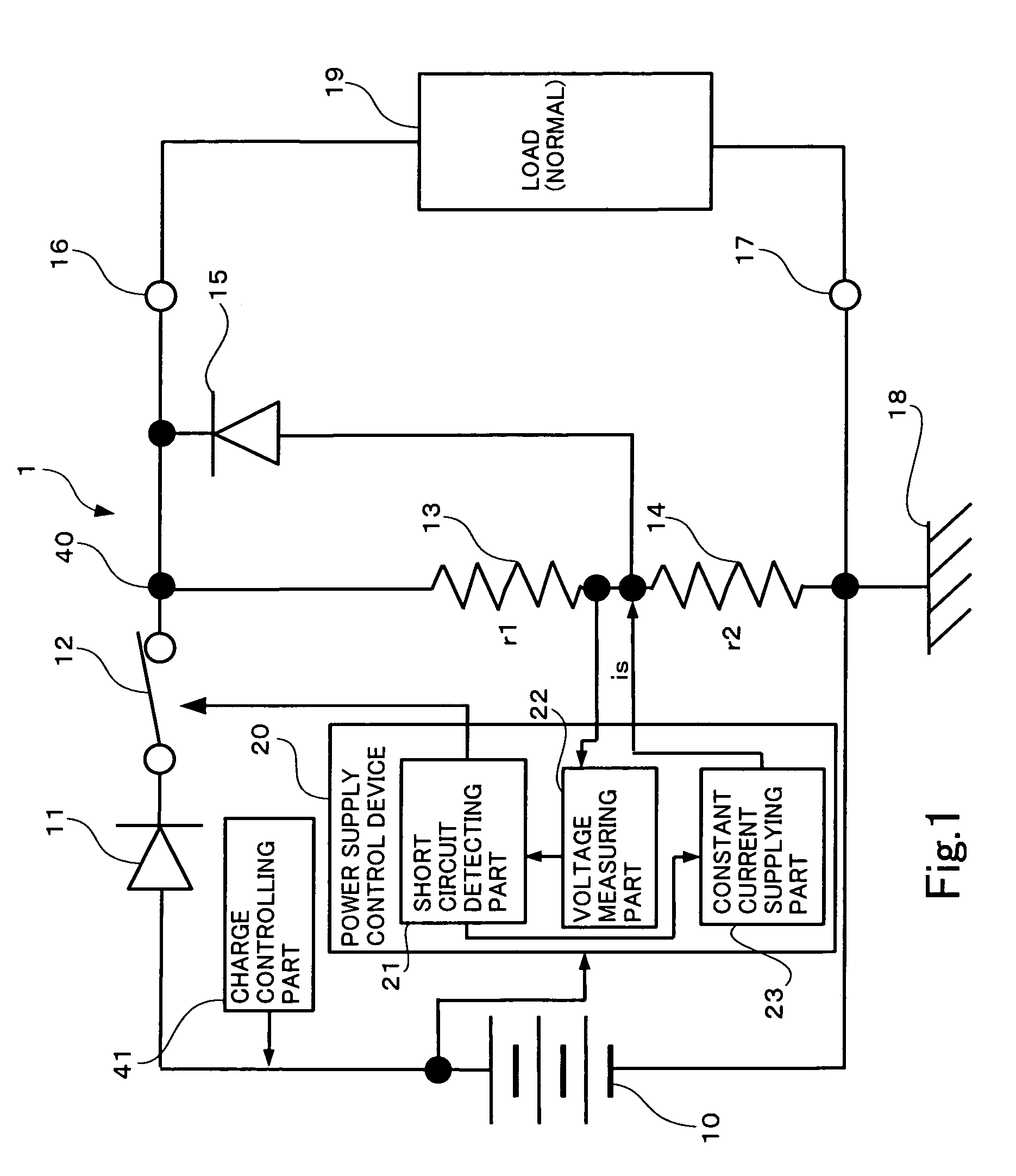
[0072]It is explained that the power supply control device 20 is configured with three function blocks, the short circuit detecting part 21, the voltage measuring part 22, and the constant current supplying part 23; however, it can also be realized by forming one electronic circuit that has these functions in the form of an Integrated Circuit (hereafter, IC).

[0073]Alternatively, the short circuit detecting part 21, the voltage measuring part 22, and the constant current supplying part 23 of the power supply control device 20 may be configured with a general information processing device (such as a central processing unit (CPU), digital signal processor (DSP), microprocessor (microcomputer), or the like) that are operated by a predetermined program. For example, the general information processing device includes a memory, a CPU, input / output port or the like. A CPU of the general information processing device reads a control program as a predetermined program from memory o...


PUM


Abstract

A power supply control device for controlling power supply to a pair of terminals to which a load is connected, comprising a voltage measuring part for measuring a voltage which has a predetermined relationship with the voltage of the pair of terminals, a short circuit detecting part for detecting whether a short circuit exists between the pair of terminals based on the measured voltage and for making power supply to the pair of terminals stop when existence of a short circuit is detected, and a constant current supplying part for supplying a constant current though the pair of terminals; wherein the short circuit detecting part is configured to detect that the previously detected short circuit is eliminated when the voltage measured by the voltage measuring part is equal to or greater than a predetermined threshold value upon supplying the constant current through the pair of terminals.

Description

CROSS-REFERENCE TO RELATED APPLICATION[0001]The present application is related to, claims priority from and incorporates by reference Japanese patent application number 2009-079798, filed on Mar. 27, 2009.BACKGROUND OF THE INVENTION[0002]1. Field of the Invention[0003]The present invention relates to a power supply control device, power supply control method, program, and power supply device.[0004]2. Description of Related Art[0005]In one example, JP H07-28532 A (patent reference 1) suggests overload protection of a power supply device. In patent reference 1, it is disclosed that an overload protection circuit stops the supply of power at the time of overload of the power supply device. Note that a general cause of an overload condition of the power supply device is when a load is short-circuited.[0006]In the overload protection circuit of patent reference 1, in order to detect whether or not the overload is eliminated, the overload condition of the power supply device is confirmed ...

Claims


Application Information

Patent Timeline
Patent Type & Authority Patents(United States)
IPC IPC(8): H02H7/00
CPCH02H3/066H02J7/0031G05F1/573H02H3/12
Inventor SENRIUCHI, TADAOHIROKAWA, MASAHIKOSAKAMOTO, TAKUMINAKAZAWA, HIROSHIHIRAO, NORIYUKI
Owner TDK LAMBDA CORP
Why Eureka
Try Eureka