Adaptor for converting a non-safety syringe into a safety syringe

a technology of adaptor and safety syringe, which is applied in the field of adaptors, can solve the problems of increasing manufacturing, distribution and stocking costs, increasing manufacturing, and increasing the cost of replacement of conventional non-safety syringes with safety syringes, and achieve the effect of preventing needle pricks

Inactive Publication Date: 2005-08-09
U S SAFETY SYRINCO
View PDF88 Cites 65 Cited by
  • Summary
  • Abstract
  • Description
  • Claims
  • Application Information

AI Technical Summary

Benefits of technology

The present invention is a new and improved safety syringe that solves the problems of previous safety syringes. It includes a shield, a spring-biased barrel, and a hub. The hub is attached to the barrel, and a ring is attached to the hub. The ring has tabs that fit into grooves in the shield to secure the barrel. This design prevents needle pricks and allows for a single use of the safety syringe. The shield, hub, spring, and ring are components of an adaptor assembly that can be added to a conventional non-safety syringe.

Problems solved by technology

The technical problem addressed in this patent text is the need to convert conventional non-safety syringes into safety syringes in a relatively inexpensive manner to prevent needle prick injuries.

Method used


Image

  • Adaptor for converting a non-safety syringe into a safety syringe
  • Adaptor for converting a non-safety syringe into a safety syringe
  • Adaptor for converting a non-safety syringe into a safety syringe

Examples


Embodiment Construction

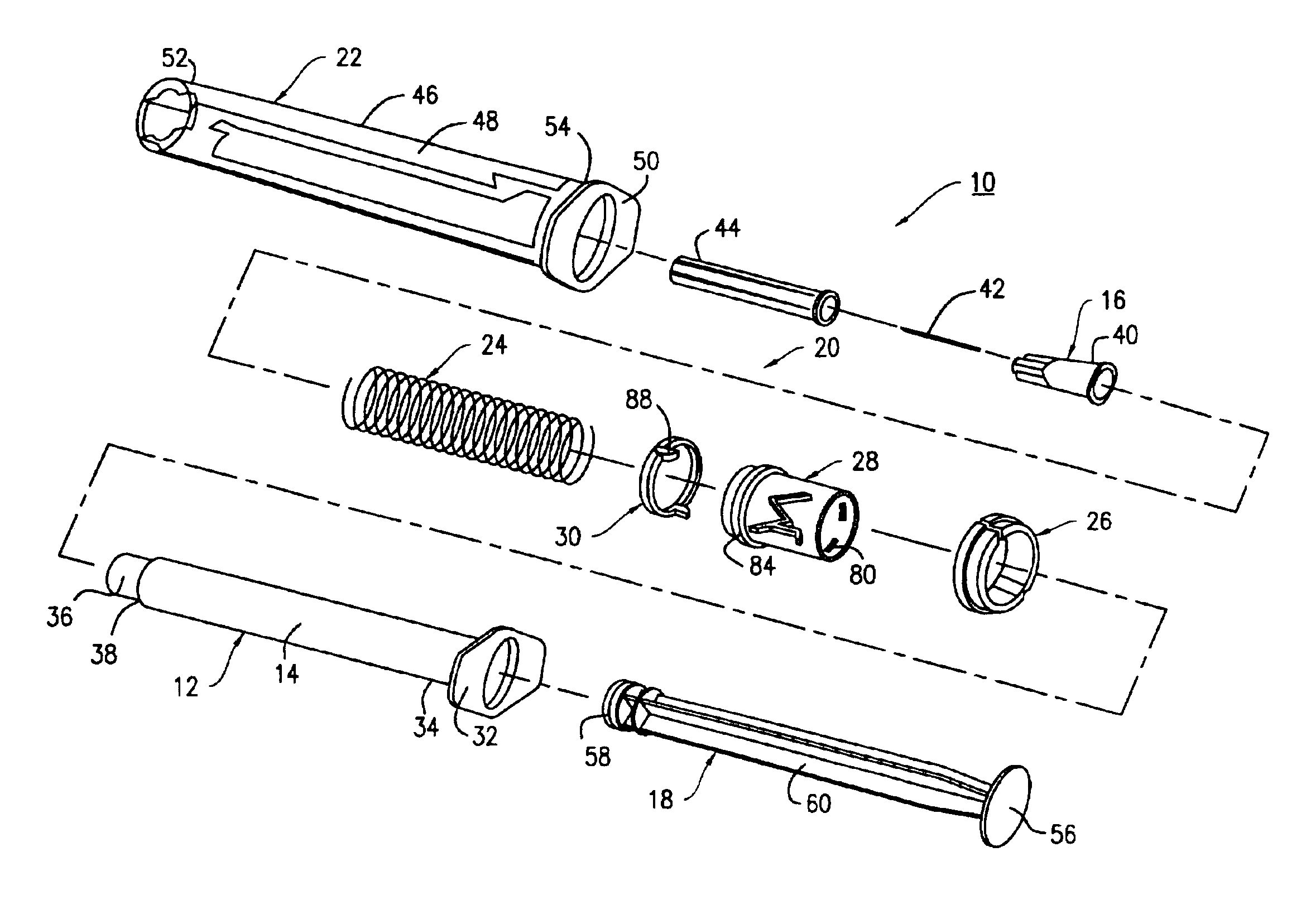
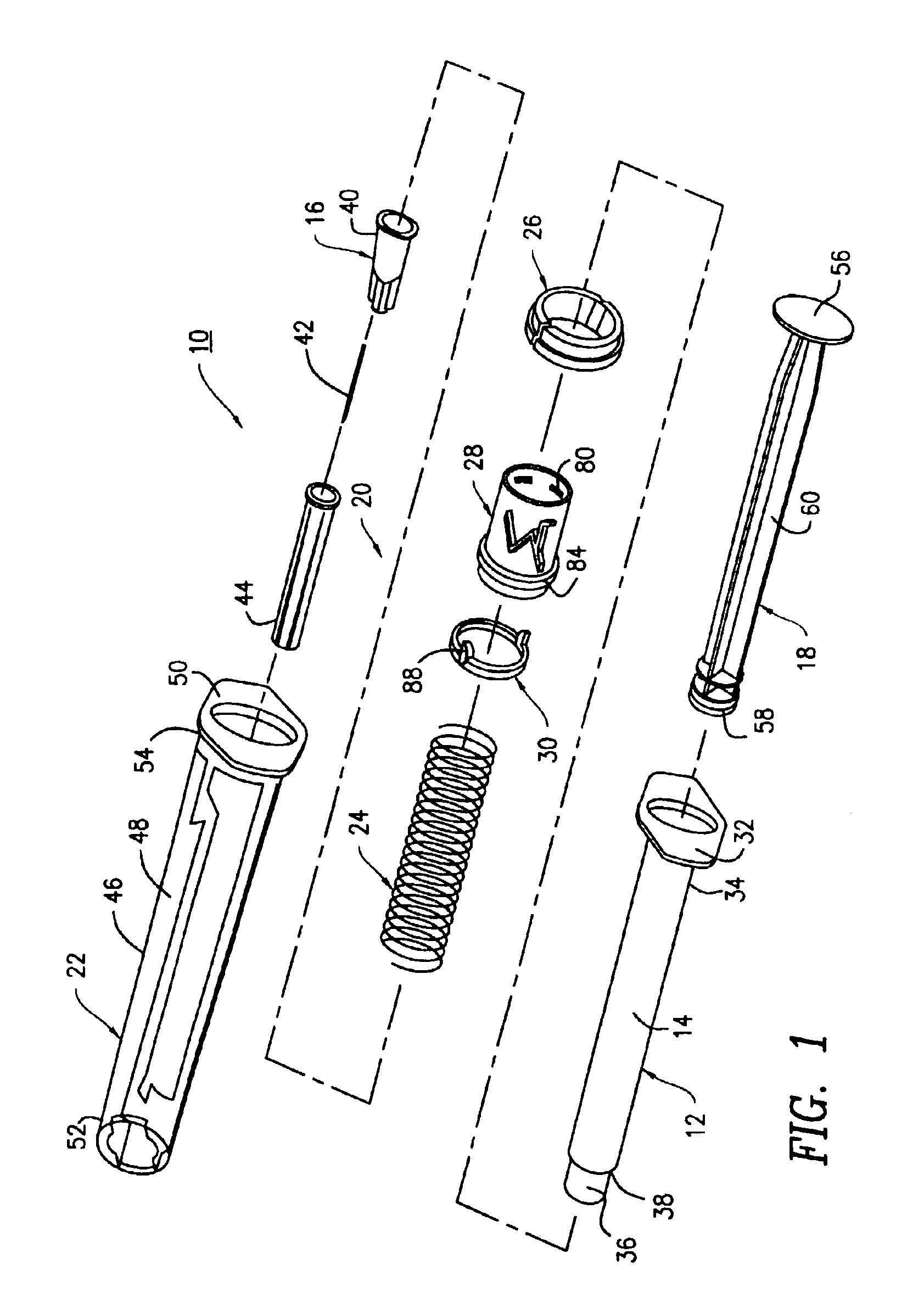
[0016]FIG. 1 illustrates a safety syringe 10 which includes a barrel 12 having a cavity 14 for storing a desired fluid (e.g., insulin). The safety syringe 10 also includes a needle assembly 16 releaseably secured to the barrel 12 and a plunger 18, which is selectively inserted into and removed from the cavity 14 of the barrel 12. In order to facilitate consideration and discussion, it is noted that the barrel 12, the needle assembly 16, and the plunger 18 are parts of a conventional non-safety syringe.

[0017]In order to overcome the disadvantages (e.g., needle prick injuries) associated with the use of a conventional non-safety syringe, the safety syringe 10 is further provided with an adaptor assembly 20 which includes a shield 22 sized and shaped so as to be coaxially received over the needle assembly 16, a helical compression spring 24 mounted within the shield 22, and a retaining bushing 26 mounted to the shield 22. The adaptor assembly 20 further includes an adaptor hub 28 sized...


PUM


Abstract

A safety syringe is provided which includes a shield and a barrel mounted for reciprocating movement within the shield. The safety syringe includes a hub sized and shaped so as to be attached to the barrel and a ring rotatably mounted to the hub. The ring includes a tab that cooperates with the grooves in the interior wall of the shield for locking the barrel within the shield so as to allow for a single use of the safety syringe.

Description


Claims


Application Information

Patent Timeline
Owner U S SAFETY SYRINCO
Why Eureka
Try Eureka