Snowplow mounting assembly

a technology for mounting parts and snowplows, which is applied in the direction of snow cleaning, way cleaning, construction, etc., can solve the problems of snow removal and achieve the effect of minimal effort and minimal amount of tim

Inactive Publication Date: 2005-08-16
DOUGLAS DYNAMICS
View PDF129 Cites 61 Cited by
  • Summary
  • Abstract
  • Description
  • Claims
  • Application Information

AI Technical Summary

Benefits of technology

[0014]Each of the stand assemblies is separately and continuously adjustable in length. This adjustable length feature enables the snowplow assembly to be placed on an uneven surface, such as a hill, in such a position that it can easily be mounted on the front of a vehicle. The driver of the vehicle may drive the receivers of the mount frame into engagement with the horns projecting rearwardly from the lift frame of the snowplow assembly. The driver then manually rotates the stand assemblies about the second transversely extending pivot axis until the latch hooks of the stand assemblies engage the latch pins of the mount frame. Thus, with minimal effort in a minimal amount of time, the driver of the vehicle may secure the snowplow assembly to the mount frame secured to the vehicle and proceed to move snow.

Problems solved by technology

Snow removal has been a problem for as long as motorized vehicles have used public roadways for transportation.

Method used


Image

  • Snowplow mounting assembly
  • Snowplow mounting assembly
  • Snowplow mounting assembly

Examples


Embodiment Construction

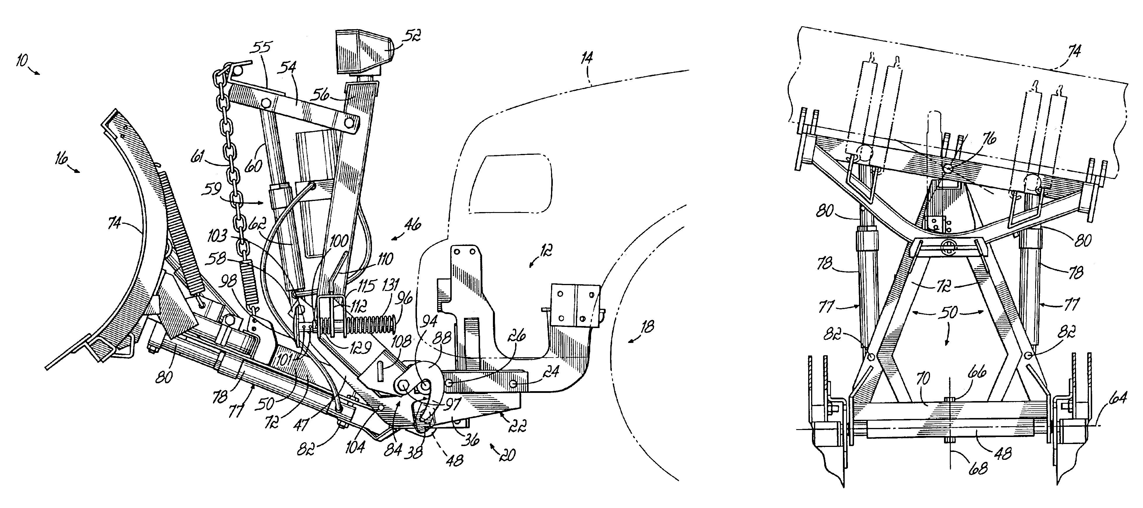
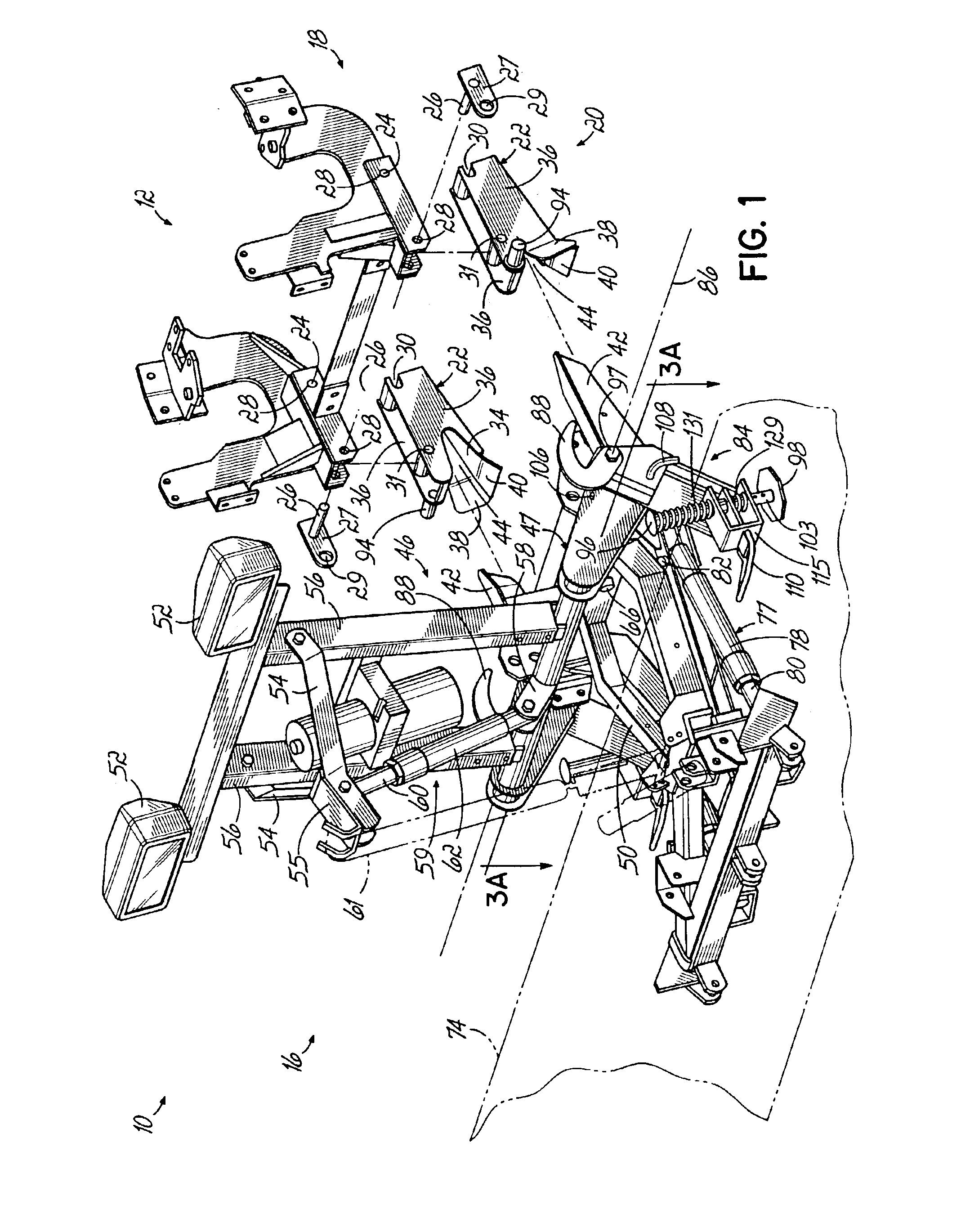
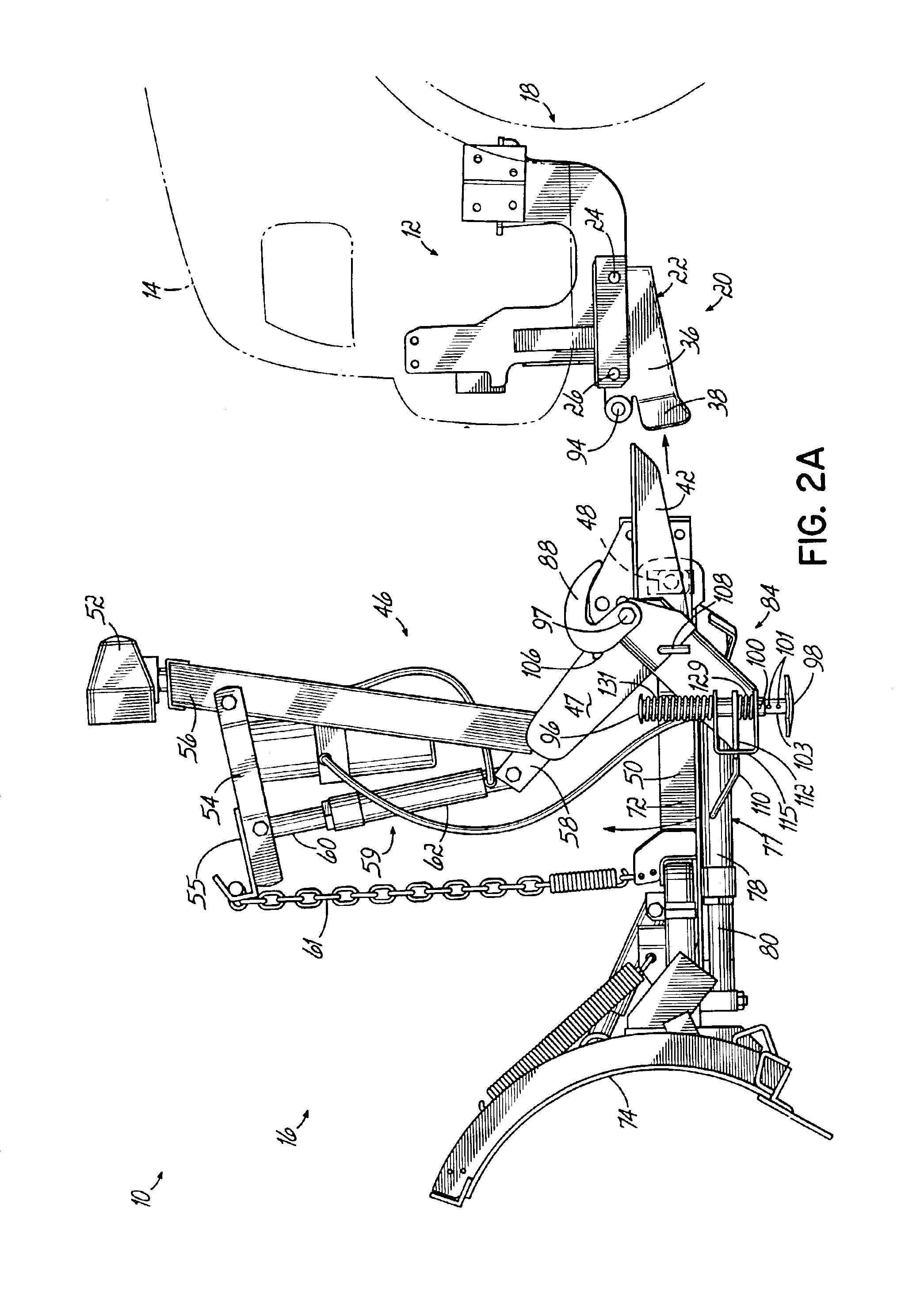
[0023]Referring to the drawings, and particularly to FIG. 1, there is illustrated a snowplow mounting assembly 10 and comprising a mount frame 12 adapted to be secured to a vehicle 14 and a snowplow assembly 16.

[0024]As best illustrated in FIG. 1, mount frame 12 comprises a first portion 18 adapted to be attached or secured to the vehicle 14 and a second portion 20 quickly and readily detachable from the first portion 18 without the use of tools, i.e. not requiring wrenches, sockets, removing nuts from bolts, etc. Such a two piece design is advantageous in order that it provides improved, i.e. increased, ground clearance of the mount frame 12 on vehicle 14, and / or increased “approach angle” of the vehicle 14, when snowplow assembly 16 is removed from the vehicle 14 during nonuse, as second portion 20 can also be removed leaving only first portion 18 mounted to the vehicle. The term approach angle refers to the angle between the horizontal road surface and a straight line extending f...


PUM


Abstract

In combination a mount frame adapted to be attached to a vehicle and a snowplow assembly. The mount frame comprises a pair of detachable receivers which receive a pair of horns extending rearwardly from the snowplow assembly. The snowplow assembly comprises an A-frame, a trunnion and a lift frame. A blade is attached to the front of the A-frame. A pair of spaced stand assemblies, each including a latching mechanism, support the snowplow assembly when the mount frame is separated from the snowplow assembly. The latching mechanisms secure the snowplow assembly to the mount frame.

Description

[0001]This application is a divisional of Ser. No. 09 / 684,269 filed Oct. 6, 2000, now U.S. Pat. No. 6,526,677 issued Mar. 4, 2003FIELD OF THE INVENTION[0002]This invention relates to snow removal equipment and, more particularly, to a snowplow mounting assembly for removably securing a snowplow to a vehicle.BACKGROUND OF THE INVENTION[0003]Snow removal has been a problem for as long as motorized vehicles have used public roadways for transportation. In response to the task of removing significant quantities of snow away from roadways, driveways and parking lots, many different types of snowplowing arrangements have been invented. Numerous of these snowplows have been configured to remove snow efficiently from a hill or other uneven surface. In addition, many of these snowplows have been built with hydraulics in order to lift the snowplow into and out of engagement with the road surface.[0004]Numerous patents disclose snowplows with one or more pivot axes. U.S. Pat. No. 3,605,906 dis...

Claims


Application Information

Patent Timeline
Patent Type & Authority Patents(United States)
IPC IPC(8): E01H5/06E01H5/04
CPCE01H5/06E01H5/066
Inventor BLOXDORF, DAVID N.BARKER, CHAD T.DOORNEK, JAMES R.KLUG, STEVEN L.RADOMSKI, STEVEN P.
Owner DOUGLAS DYNAMICS
Why Eureka
Try Eureka