Crawler shoe with peening pads in roller path

a technology of peening pads and roller paths, which is applied in the field of claw shoes, can solve the problems of deformation material on the top surface of the roller path not being balanced by the supporting material under the roller path, interference between shoes, and cracking on the internal core, so as to inhibit the shoe from slipping, eliminate severe elongation and residual compressive stresses, and eliminate high compressive residual stress

Active Publication Date: 2005-08-16
JOY GLOBAL SURFACE MINING INC
View PDF8 Cites 20 Cited by
  • Summary
  • Abstract
  • Description
  • Claims
  • Application Information

AI Technical Summary

Benefits of technology

[0006]One of the principal objects of the invention is to eliminate high compressive residual stress in the roller path after work hardening of the roller path.
[0007]Another of the principal objects of the invention is to eliminate severe elongation and residual compressive stresses that can result in gross geometrical changes to the crawler shoes. These changes can cause interference between shoes, known as binding, or back bending, which is when the entire shoe bends downward at the ends. When back bending is severe enough, it can inhibit the shoes from hinging because the pins are no longer on a common axis.

Problems solved by technology

On some shoes, it has been found that the plastic flow on the surface of the roller path is responsible for cracking on the internal cores under the roller path of the shoes.
In severe cases, the deformed material on the top surface of the roller path can not be balanced by the supporting material under the roller path.
These changes can cause interference between shoes, known as binding, or back bending, which is when the entire shoe bends downward at the ends.
When back bending is severe enough, it can inhibit the shoes from hinging because the pins are no longer on a common axis.

Method used


Image

  • Crawler shoe with peening pads in roller path
  • Crawler shoe with peening pads in roller path
  • Crawler shoe with peening pads in roller path

Examples


Embodiment Construction

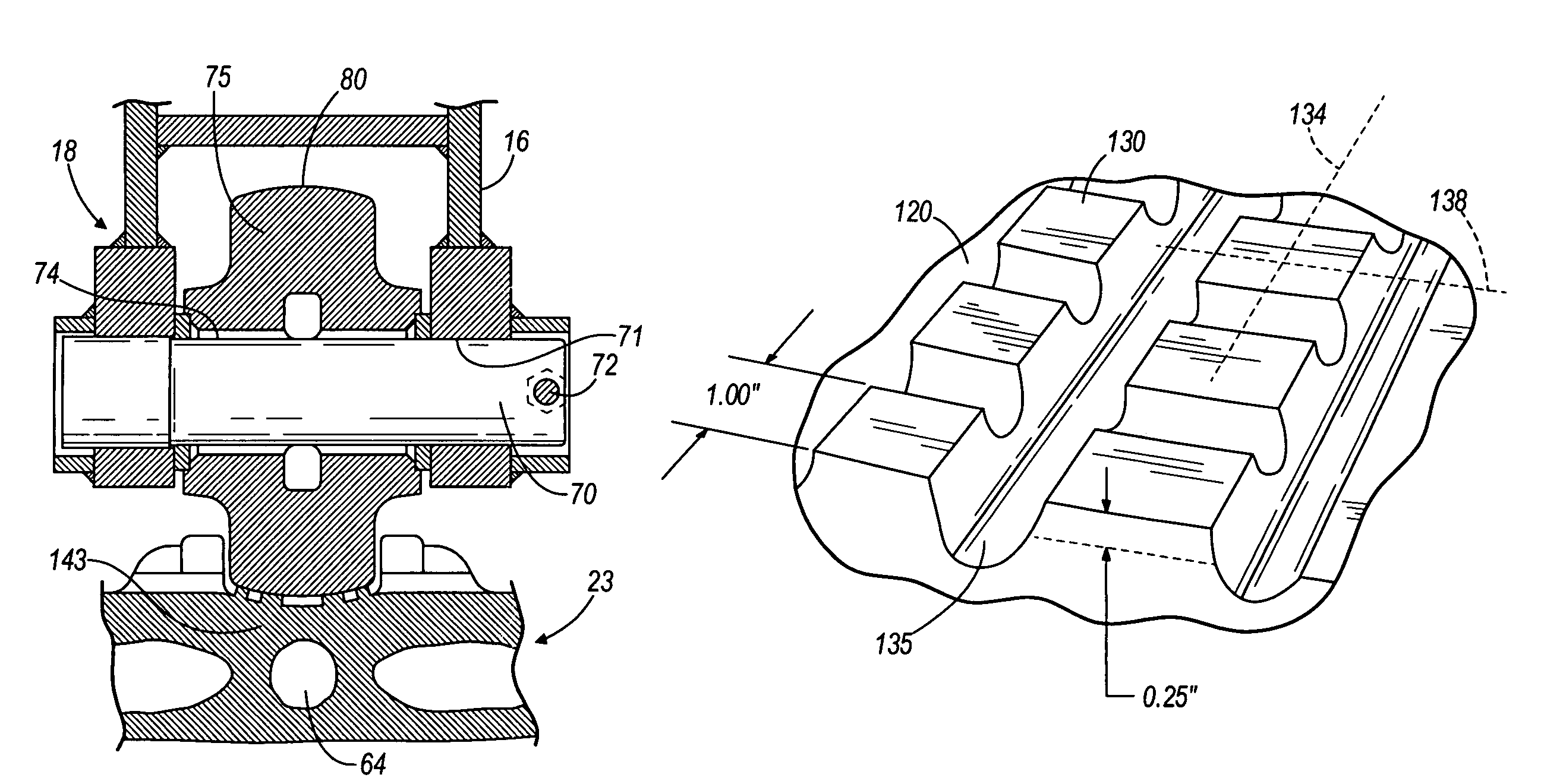
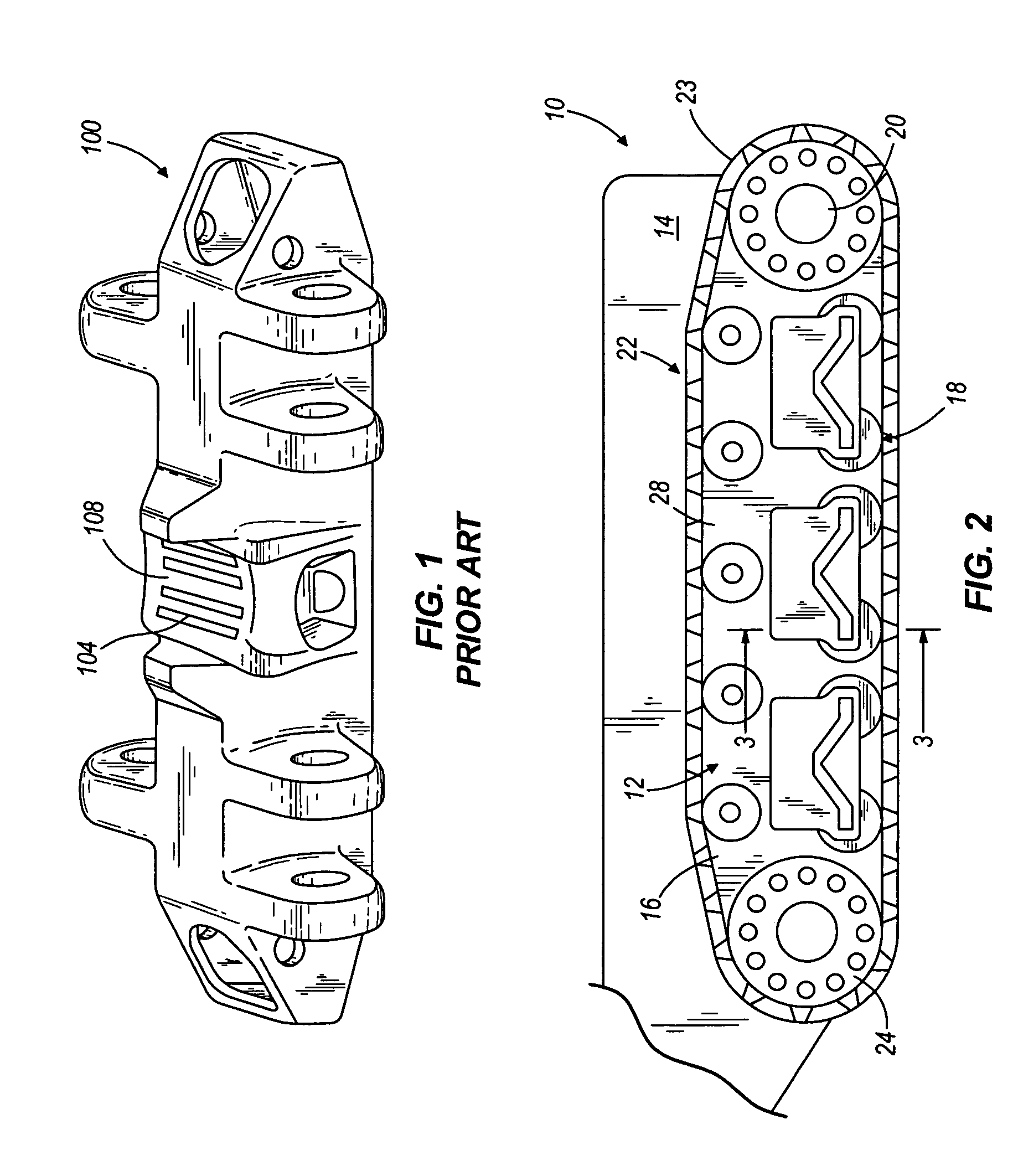
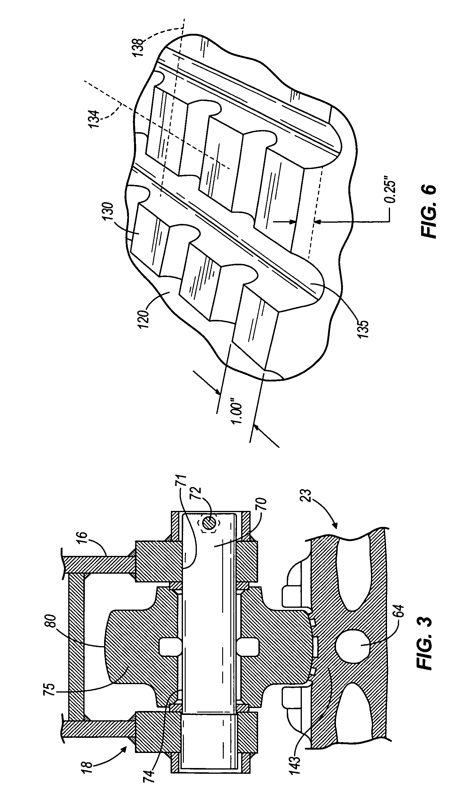
[0016]FIG. 2 shows a schematic illustration of part of a machine 10, such as an electric shovel, with an endless crawler track 22. The machine 10, which if an electric shovel, is on the order of seventy feet high and weighs about 500 to 1600 tons, comprises a lower section 12 and a rotatable upper section 14 mounted thereon. Lower section 12 comprises a crawler frame 16 on which are mounted a plurality of crawler roller assemblies 18 and propelling machinery 20. The crawler track 22 is mounted on the roller assemblies 18 and on the propelling machinery 20. Another crawler track (not shown) is used on the backside of the lower section 12 shown in FIG. 2. Referring to FIG. 2, the crawler track 22 is driven by the propelling machinery 20 in a conventional manner by a crawler drive tumbler 24.

[0017]The crawler track 22 comprises a plurality of crawler shoes 23 which are identical to one another. Adjacent shoes 23 are connected to one another by means of removable, replaceable pins 27 (o...


PUM

PropertyMeasurementUnit
weightaaaaaaaaaa
toughnessaaaaaaaaaa
hardnessaaaaaaaaaa

Abstract

Each crawler shoe comprises a main body having an upper surface, a lower surface, and opposite lateral sides and opposite front and rear sides. Each crawler shoe further includes a mechanism on the main body for articulately and releasably connecting the crawler shoe to an adjacent crawler shoe. Each crawler shoe further includes a roller path on the upper surface of the main body and drive lugs attached to the upper surface of the main body on opposite sides of the roller path. Each crawler shoe further includes an upward extending peening portion so that when a downward force is applied to the peening portion, unrestricted metal flow at the peening portion can occur in a first horizontal direction and in a second horizontal direction greater than 45 degrees from the first horizontal direction. More particularly, the peening portion is greater than 0.1 inch tall, and, in the preferred embodiment, about 0.25 inches tall.

Description

BACKGROUND OF THE INVENTION[0001]This invention relates to crawler shoes used in crawler tracks for mining shovels or other heavy-duty equipment.[0002]Electric mining shovels use an endless belt of crawler shoes to both distribute the weight of the machine on the ground and to transverse uneven ground conditions. Each shoe must be capable of supporting up to one half of the weight of the machine. The crawler shoes are subjected to wear and tear resulting from operation in dust, mud, rock and highly abrasive soils, shock loads, and other severe operating conditions. Adjacent shoes in a crawler track are connected to one another by means of removable, replaceable pins that permit articulation of adjacent shoes and also enable the shoes to be replaced as they become worn. Such crawler shoes are relatively large, being on the order of seven feet wide, for example, and heretofore have been made by casting steel. In a typical crawler track, heavy-duty forged or cast steel rollers ride upo...

Claims


Application Information

Patent Timeline
Patent Type & Authority Patents(United States)
IPC IPC(8): B62D55/20B62D55/26B62D55/14B62D55/18
CPCB62D55/14B62D55/202B62D55/26
Inventor COLWELL, JOSEPH J.BORKOWSKI, GARY R.
Owner JOY GLOBAL SURFACE MINING INC
Why Eureka
Try Eureka