Ground bar

a ground bar and guiding function technology, applied in the field of ground bars, can solve the problems of serious environmental problems, loss of grounding function, deterioration of electric guiding function of conventional ground bars, etc., and achieve the effect of smooth extension into the ground

Active Publication Date: 2005-08-16
CHEN KUO HSIUNG
View PDF18 Cites 12 Cited by
  • Summary
  • Abstract
  • Description
  • Claims
  • Application Information

AI Technical Summary

Benefits of technology

[0007]The primary objective of the invention is to provide a ground bar that can smoothly extend into the ground and protect...

Problems solved by technology

Due to the swell of the stick periphery, the brass layer 7 is broken and therefore the electricity guiding function of the conventional ground bar is deteriorated.
Besides, the leakage of chemical solution from the brass plating process as a consequence of the broken brass layer 7 will cause serious environment problem.
From the aforementioned description, it is no...

Method used


Image

  • Ground bar
  • Ground bar
  • Ground bar

Examples


Embodiment Construction

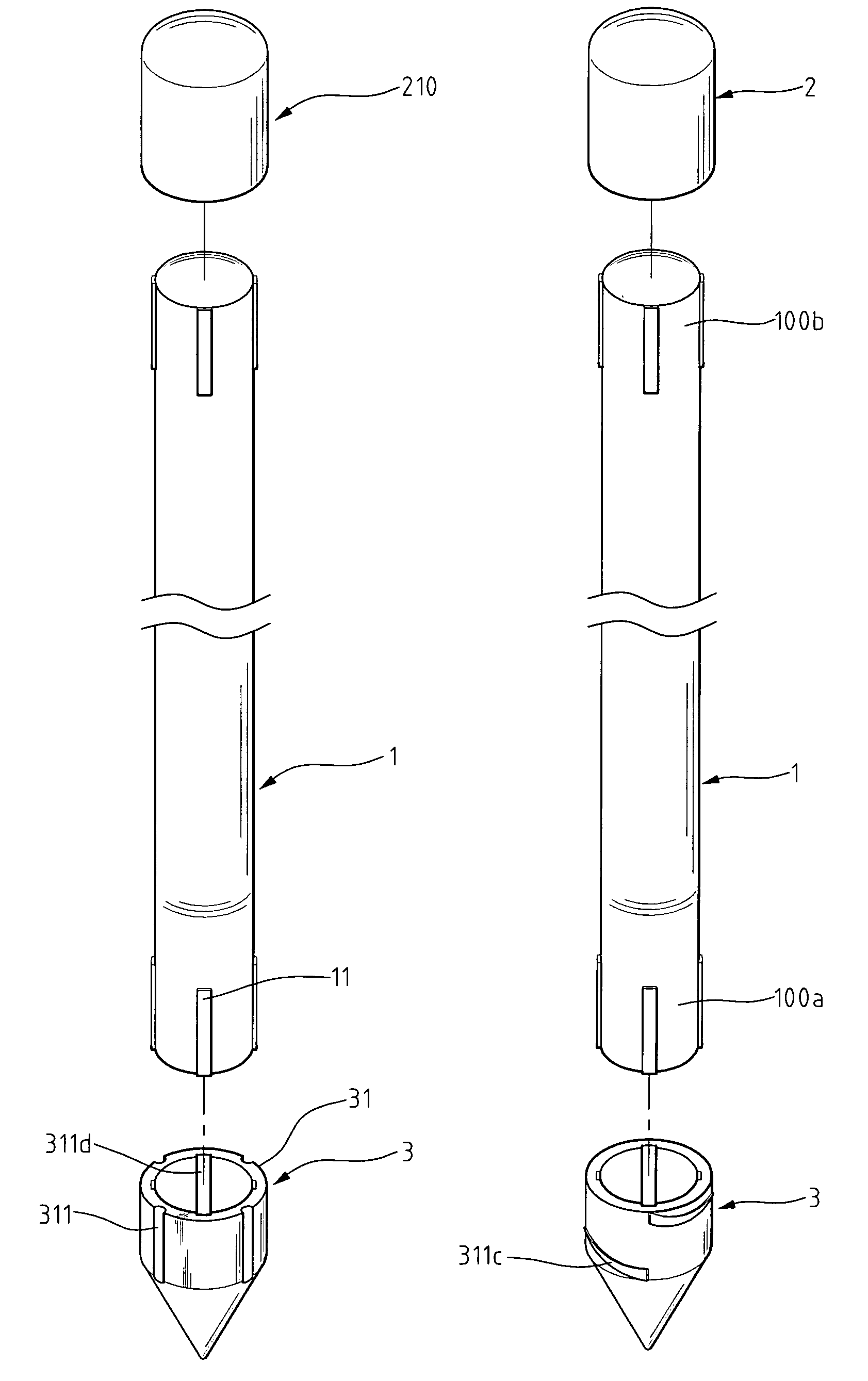
[0025]With reference to FIG. 3, a ground bar in accordance with the present invention comprises a bar 1, a cap 2, and a head 3. The bar 1 is made of metal and has a first end to be connected to the head 3 and a second end to be connected to the cap 2.

[0026]The head 3 is a combination of a sleeve 31 and a cone 32. The sleeve 31 is hollow and has multiple slits 311 longitudinally defined in the outer periphery of the sleeve 31. The cone 32 is solid. The sleeve 31 further has an outer diameter larger than the diameter of the bar 1.

[0027]With reference to FIGS. 3A–3G, the sleeve 31 may assume different cross-sectional shape, such as a cylinder having a smooth outside periphery (reference 31, FIG. 3A), or having a polygonal outer periphery (reference 31a, FIG. 3B), or having a smooth outer periphery with a pattern which may be slits 311 (FIG. 3C), V-shaped slits 311b (FIG. 3D) or a spiral slit 311c (FIG. 3E). Also, the cone 32 may have a smooth outer periphery 32a (FIG. 3F) or a polygona...


PUM


Abstract

A ground bar includes a bar, a head securely connected to a first end of the bar, and a cap securely connected to a second end of the bar. The head is composed of a solid cone and a hollow sleeve securely connected to the solid cone and having a diameter larger than a diameter of the bar in such way that the outer periphery of the bar is protected so that after the head is extended into the ground, the outer periphery of the bar is protected from damage. The outer periphery of the hollow sleeve has slits defined thereon for guiding dirt.

Description

BACKGROUND OF THE INVENTION[0001]1. Field of the Invention[0002]The present invention relates to a ground bar, and more particularly to a ground bar that maintains completeness of its outer periphery so as to effectively guide abnormal electrical currents to the ground.[0003]2. Description of Related Art[0004]A ground bar is designed to guide abnormal electrical current, such as lightning, to the ground to prevent any damage to the electrical appliance from the abnormal electrical current. With reference to FIGS. 1, 2, and 2A, a conventional ground bar is introduced and has a stick 2, a cap 3 securely mounted on top of the stick 2 and a conical head 4 securely mounted on a bottom end of the stick 2. In order to effectively guide the electrical current to the ground by the so-called “skin effect”, the material for the cap 3 and the conical head 4 preferably is metal. Further a brass layer 7 is plated onto the outer periphery of the stick 2. It is to be noted that the conical head 4 h...

Claims


Application Information

Patent Timeline
IPC IPC(8): H01R4/66
CPCH01R4/66
Inventor CHEN, KUO-HSIUNG
Owner CHEN KUO HSIUNG
Why Eureka
Try Eureka