Power supply device for energizing discharge lamp

Active Publication Date: 2005-08-16
SHARP NEC DISPLAY SOLUTIONS LTD
View PDF5 Cites 0 Cited by
  • Summary
  • Abstract
  • Description
  • Claims
  • Application Information

AI Technical Summary

Benefits of technology

[0038]It is an object of the present invention to provide a discharge lamp energizing power supply device which is operable to reduce an electric power loss in a wide range of commercial power supply voltages employed in various parts of the world, and which can stably perform its functions without causing a functional shutdown of a boosting circuit due to an increase in the power supply voltage and a functional shutdown of a voltage lowering circuit due to a characteristic deterioration of a discharge lamp.
[0046]Since the boosted voltage changing circuit can improve the power factor of the power-factor improve based on the rectified voltage EO at its input side, it is possible to set voltage boosting ratios for achieving successively effective high power factors with respect to a wide range of commercial power supplies from a commercial power supply of a lowest voltage, e.g., AC 100 V, to a commercial power supply of a highest voltage, e.g., AC 240 V. Because a functional shutdown of the voltage lowering circuit can be avoided when the boosted voltage changing circuit sets the activating output voltage VO in a continuous functional range of the voltage lowering circuit based on the discharging voltage or energizing output voltage VL. The discharge lamp energizing power supply device according to the present invention is thus continuously energizing the discharge lamp.

Problems solved by technology

When the input power supply voltage is low, the voltage boosting ratio is very high, resulting in an increase in the power consumption and heat loss.
However, the conventional discharge lamp energizing power supply device is not suitable for use as a general-purpose power supply device which operates efficiently in a wider range of power supply voltages, e.g., a range from AC 100 V that is used in Japan to AC 240 V that is used in Europe.

Method used


Image

  • Power supply device for energizing discharge lamp
  • Power supply device for energizing discharge lamp
  • Power supply device for energizing discharge lamp

Examples


Embodiment Construction

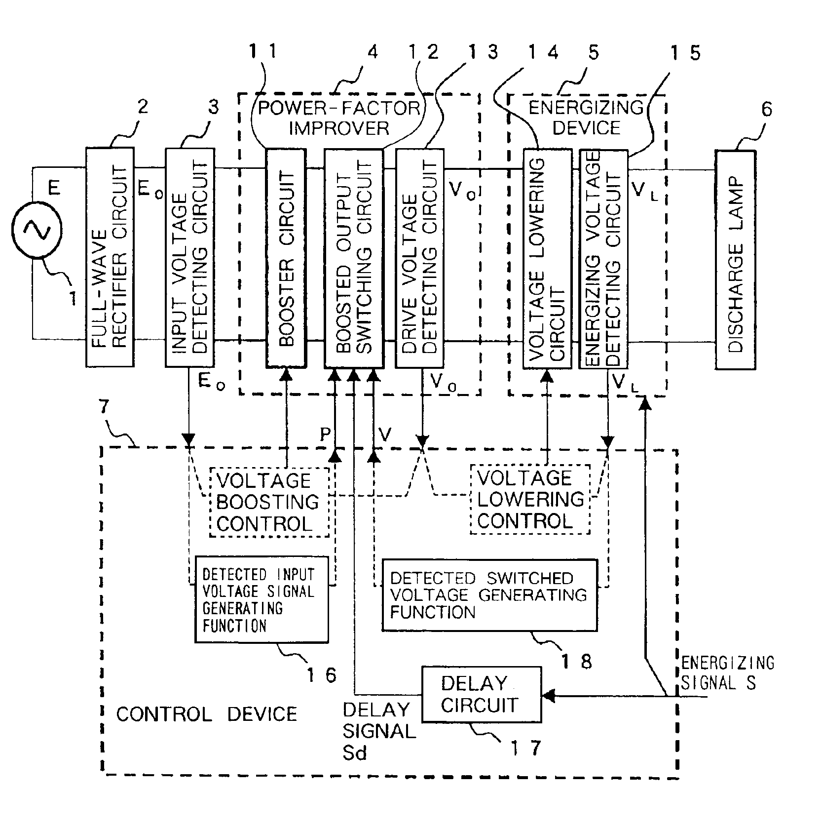
[0056]FIG. 5 shows in block form a basic arrangement of a discharge lamp energizing power supply device according to an embodiment of the present invention.

[0057]As shown in FIG. 5, the discharge lamp energizing power supply device (hereinafter referred to as “power supply device”) comprises an AC / DC converter including full-wave rectifier circuit 2 for converting an input AC voltage E obtained from commercial AC power supply system 1 into a full-wave rectified waveform and booster circuit 11 for improving the power factor, the AC / DC converter boosting a rectified voltage value EO which is a maximum value of the full-wave rectified waveform and outputting the boosted voltage value for turning on discharge lamp 6 with an electric discharge therein, and a non-insulated DC / DC converter including voltage lowering circuit 14 for lowering the boosted voltage and outputting the lowered voltage to keep discharge lamp 6 energized after discharge lamp 6 is turned on by the electric discharge ...


PUM


Abstract

A discharge lamp energizing power supply device has a full-wave rectifier circuit for rectifying an AC voltage obtained from a commercial AC power supply system into a full-wave rectified waveform, a booster circuit for boosting the voltage of the full-wave rectified waveform, a boosted-voltage changing circuit for changing the boosted voltage output from the booster circuit, a voltage lowering circuit for lowering an output voltage from the boosted-voltage changing circuit and outputting an activating output voltage for activating a discharge lamp and an energizing output voltage for keeping the discharge lamp energized, and a control device for controlling a boosted voltage in the boosted-voltage changing circuit within a predetermined range based on the voltage of the full-wave rectified waveform when the voltage lowering circuit outputs the energizing output voltage.

Description

BACKGROUND OF THE INVENTION[0001]1. Field of the Invention[0002]The present invention relates to a discharge lamp energizing power supply device having a full-wave rectifier circuit for rectifying an AC voltage obtained from a commercial AC power supply system into a full-wave rectified waveform, a booster circuit for boosting the voltage of the full-wave rectified waveform, a boosted-voltage changing circuit for changing the boosted voltage output from the booster circuit, and a voltage lowering circuit for lowering an output voltage from the boosted-voltage changing circuit and outputting an activating output voltage for activating a discharge lamp to turn on the discharge lamp and an energizing output voltage for keeping the discharge lamp energized, and more particularly to a discharge lamp energizing power supply device for reducing a power loss for increased efficiency with respect to a wide range of power supply voltages and keeping a discharge lamp energized stably even when...

Claims


Application Information

Patent Timeline
IPC IPC(8): H05B41/292H05B41/282H05B41/28H05B41/288H02M3/155H02M7/12
CPCH05B41/282H05B41/2886H05B41/2923Y02B20/208Y10S315/04Y02B20/00
Inventor HOSONO, HIDEAKI
Owner SHARP NEC DISPLAY SOLUTIONS LTD
Why Eureka
Try Eureka