Automotive fuel supply apparatus

Inactive Publication Date: 2005-10-04
MITSUBISHI ELECTRIC CORP
View PDF24 Cites 23 Cited by
  • Summary
  • Abstract
  • Description
  • Claims
  • Application Information

AI Technical Summary

Benefits of technology

[0032]Therefore, provided is an inexpensive automotive fuel supply apparatus enabling electric power losses to be reduced by reducing unnecessary fu

Problems solved by technology

Thus, electric power generated in an alternator (not shown) by driving the engine 5 is consumed wastefully by the fuel pump 1 operating at this maximum-output setting, resulting in the consumption of fuel being increased.
Furthermore, it is necessary for the fuel injection valves 4 to inject 0.055 cc of fuel within five milliseconds in each injection, but when injection capacity is low, injection may take longer than five milliseconds.
However, in the conventional fuel supply apparatus proposed as an improvement, the quantity of flow between point C and point E when one fuel injection valve 4 is open, and between point D and point E when the fuel injection valves 4 are closed is still discharged wastefully by the fuel pump 1, making the recovery of losses insufficient.
Furthermore, because the voltage (14 V) from the battery 15 is dropped to 12 V by the resistor 17 before

Method used


Image

  • Automotive fuel supply apparatus
  • Automotive fuel supply apparatus
  • Automotive fuel supply apparatus

Examples


embodiment 1

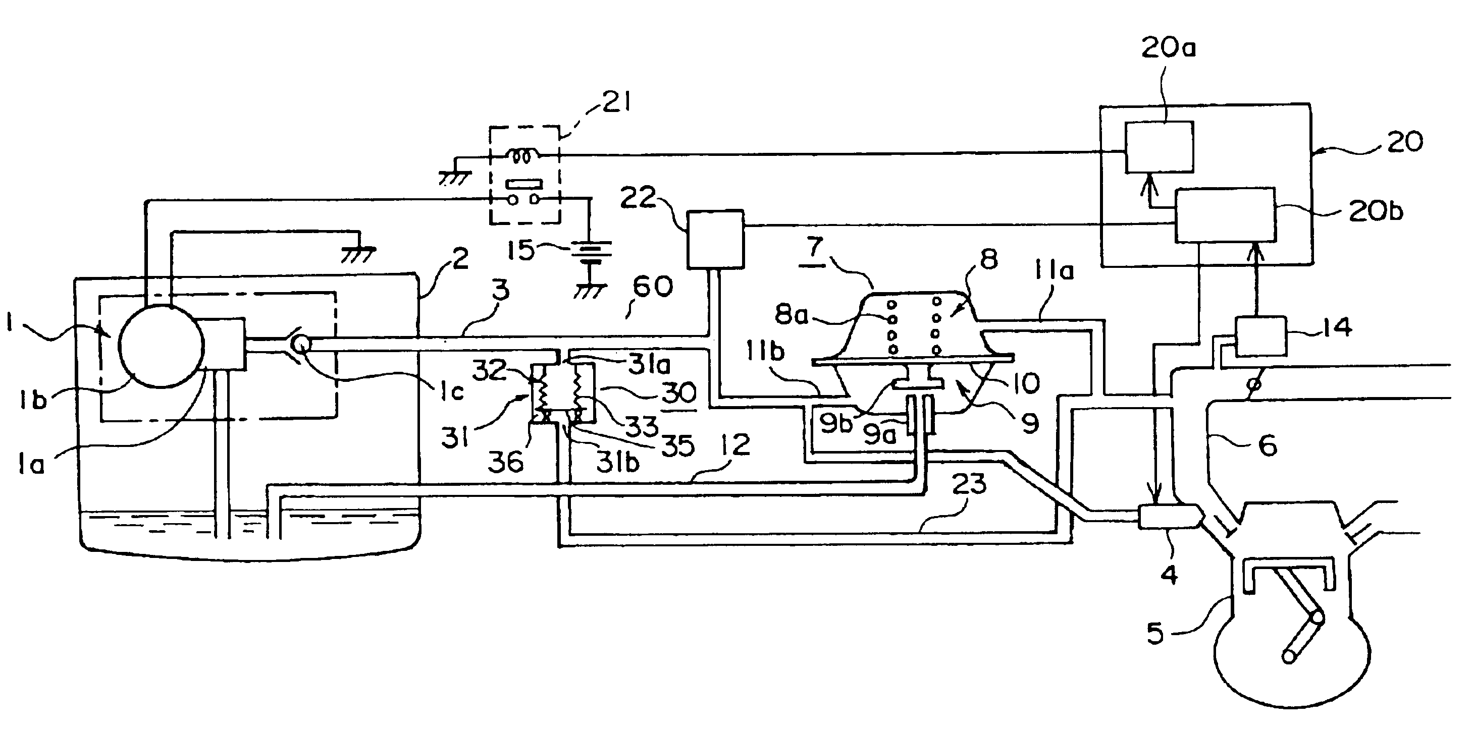
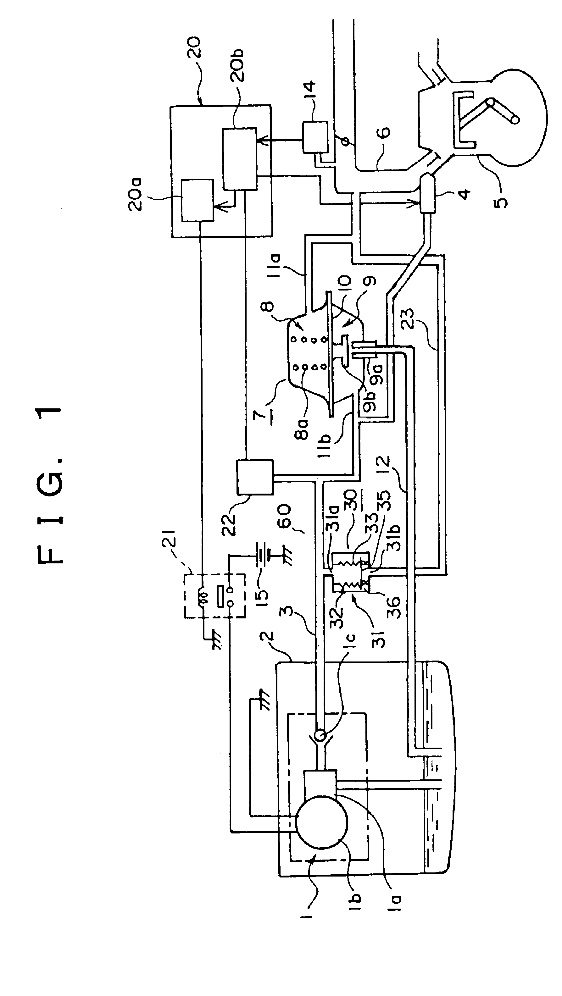
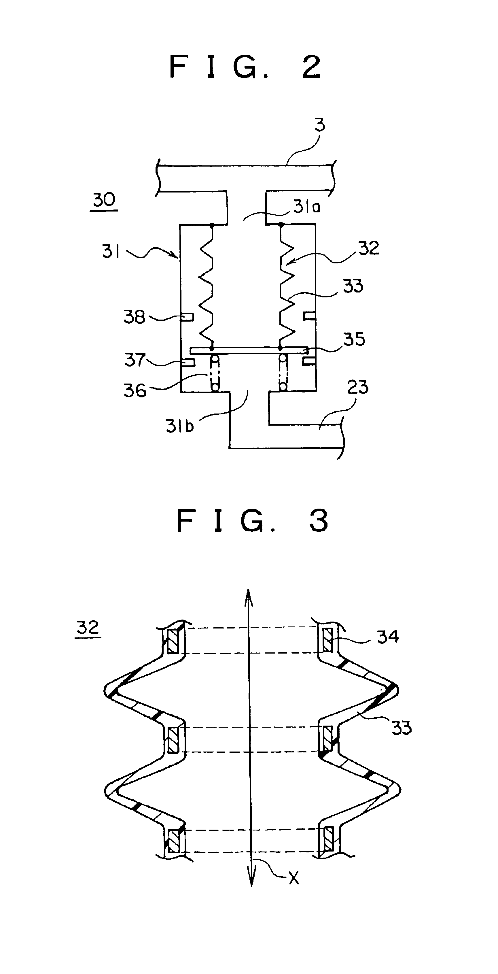
[0046]FIG. 1 is a schematic diagram showing a general overview of an automotive fuel supply apparatus according to Embodiment 1 of the present invention, FIG. 2 is a schematic diagram showing a construction of a pressure accumulator of the automotive fuel supply apparatus shown in FIG. 1, and FIG. 3 is a partial enlarged cross section of FIG. 2.

[0047]Moreover, in FIG. 1, portions identical to or corresponding to those in the conventional automotive fuel supply apparatuses shown in FIGS. 9, 11, and 12 will be given the same numbering, and explanation thereof will be omitted.

[0048]In FIG. 1, an engine control apparatus 20 is provided with a pump control portion 20a and a fuel computing control portion 20b. A fuel pressure detector 22 is connected to a fuel distribution line 3, detecting the pressure of the fuel inside the fuel distribution line 3 and outputting a pressure detection signal to the engine control apparatus 20. A pressure accumulator 30 is disposed inside an engine compar...

embodiment 2

[0088]FIG. 4 is a schematic diagram showing a construction of a pressure accumulator of an automotive fuel supply apparatus according to Embodiment 2 of the present invention.

[0089]In FIG. 4, a pressure accumulator 30A is provided with: a tubular housing 31 in which a first aperture 31a and a second aperture 31b are disposed; a storage chamber 40 constructed such that an internal volume thereof is expandable and contractable, connected airtightly to an inner wall of the housing 31 so as to communicate with the first aperture 31a; and an accumulator spring 42 functioning as a pressure applying means for forcing the storage chamber 40 in a direction of contraction, disposed in a compressed state between an end plate 35 of the storage chamber 40 and a bottom surface of the housing 31. The pressure accumulator 30A is connected to the fuel distribution line 3 through the first aperture 31a and communicates with a portion of an intake air manifold 6 upstream from fuel injection valves 4 t...

embodiment 3

[0099]FIG. 5 is a schematic diagram showing a construction of a pressure accumulator of an automotive fuel supply apparatus according to Embodiment 3 of the present invention, and FIG. 6 is a partial enlarged cross section of FIG. 5.

[0100]In FIG. 5, a pressure accumulator 30B is provided with: a tubular housing 31 in which a first aperture 31a and a second aperture 31b are disposed; and a storage chamber 43 constructed such that an internal volume thereof is expandable and contractable, connected airtightly to an inner wall of the housing 31 so as to communicate with the first aperture 31a. The pressure accumulator 30B is connected to the fuel distribution line 3 through the first aperture 31a and communicates with a portion of an intake air manifold 6 upstream from fuel injection valves 4 through the second aperture 31b and a communicating line 23.

[0101]The storage chamber 43, as shown in FIG. 6, is constituted by: a welded-disk bellows 44 functioning as a partition wall prepared b...


PUM


Abstract

A fuel pressure detector and a pressure accumulator are disposed in a fuel distribution line, an engine control apparatus controlling activation of a fuel pump based on output from the fuel pressure detector. The fuel pump is activated at maximum capacity to fill the fuel distribution line with fuel at a controlled pressure controlled by a fuel pressure regulator, then stopped. In this state, fuel accumulated under pressure in the pressure accumulator replenishes the fuel distribution line until fuel pressure inside the fuel distribution line drops to a predetermined value due to fuel injection by fuel injection valves.

Description

BACKGROUND OF THE INVENTION[0001]1. Field of the Invention[0002]The present invention relates to a fuel supply apparatus for an automotive engine and particularly relates to an automotive fuel supply apparatus for reducing engine fuel consumption.[0003]2. Description of the Related Art[0004]FIG. 9 is a schematic diagram showing a general overview of a conventional automotive fuel supply apparatus.[0005]In FIG. 9, a fuel pump 1 is disposed inside a fuel tank 2 and is connected to a fuel injection valve 4 of an engine 5 by a fuel distribution line 3. The fuel pump 1 is provided with: a pump main body portion 1a; an electric motor portion 1b for driving the pump main body portion 1a; and a check valve 1c for improving engine starting by keeping a fuel system including the fuel distribution line 3 charged with fuel when the engine 5 is stopped. Furthermore, a switching relay 16 is controlled by a pump control portion 13a of an engine control apparatus 13 described below such that a volt...

Claims


Application Information

Patent Timeline
IPC IPC(8): F02M69/46F02M55/04F02M55/00F02M69/54F02D41/30F02M37/10F02M37/08F02M37/00F02D33/00F02D41/20
CPCF02D33/006F02D41/3082F02M37/0052F02M37/10F02M55/00F02M55/04F02M69/462F02M69/54F02D2200/0602F02D2250/31F02M2037/087
Inventor KISHIMOTO, YUJI
Owner MITSUBISHI ELECTRIC CORP
Why Eureka
Try Eureka