Measurement device and seating arrangement
a measurement device and seating arrangement technology, applied in the direction of force/torque/work measurement apparatus, simultaneous indication of multiple variables, tractors, etc., can solve the problem of longer service life of the measurement assembly, and achieve the effect of precise and reliable force measuremen
- Summary
- Abstract
- Description
- Claims
- Application Information
AI Technical Summary
Benefits of technology
Problems solved by technology
Method used
Image
Examples
first embodiment
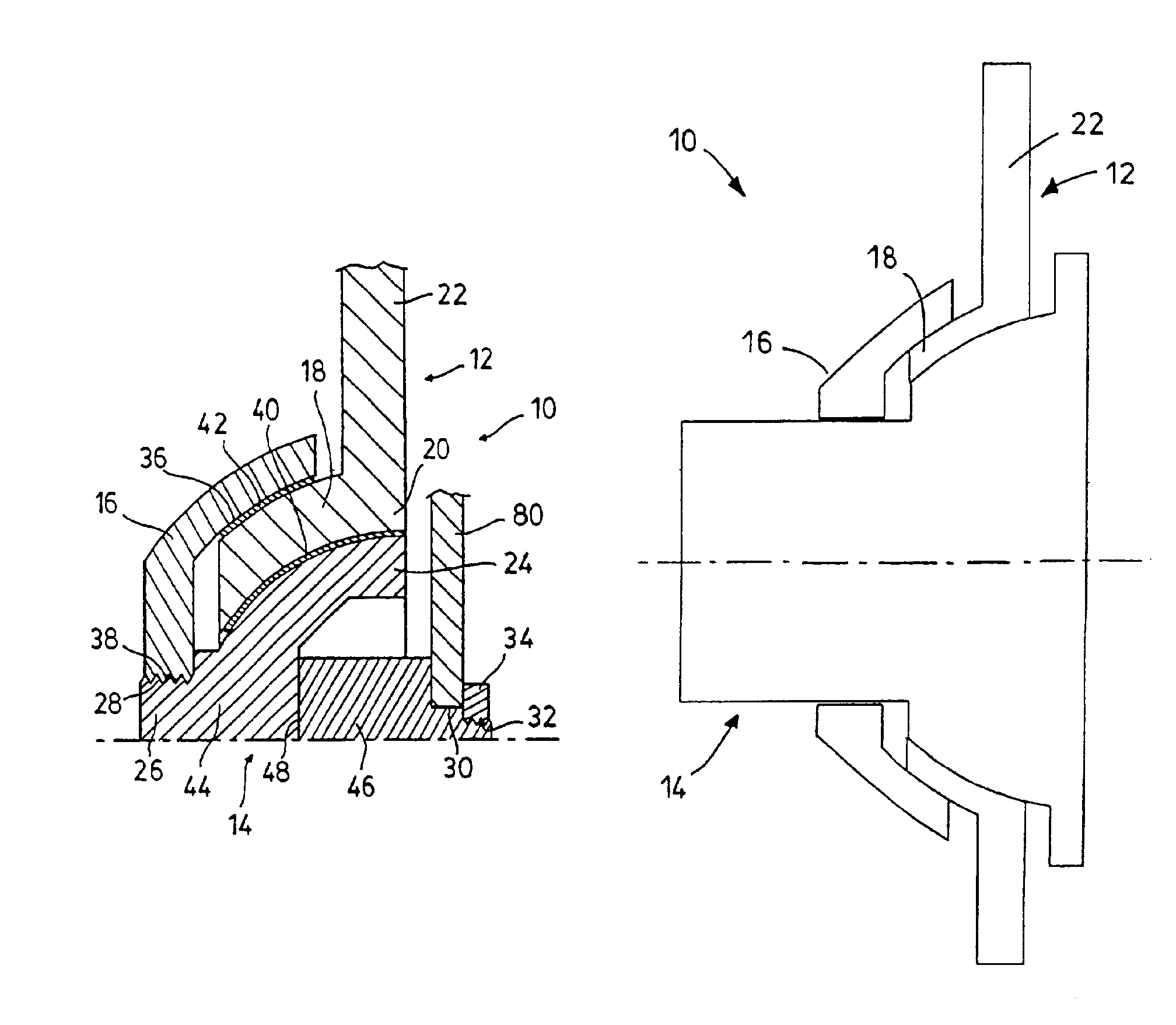
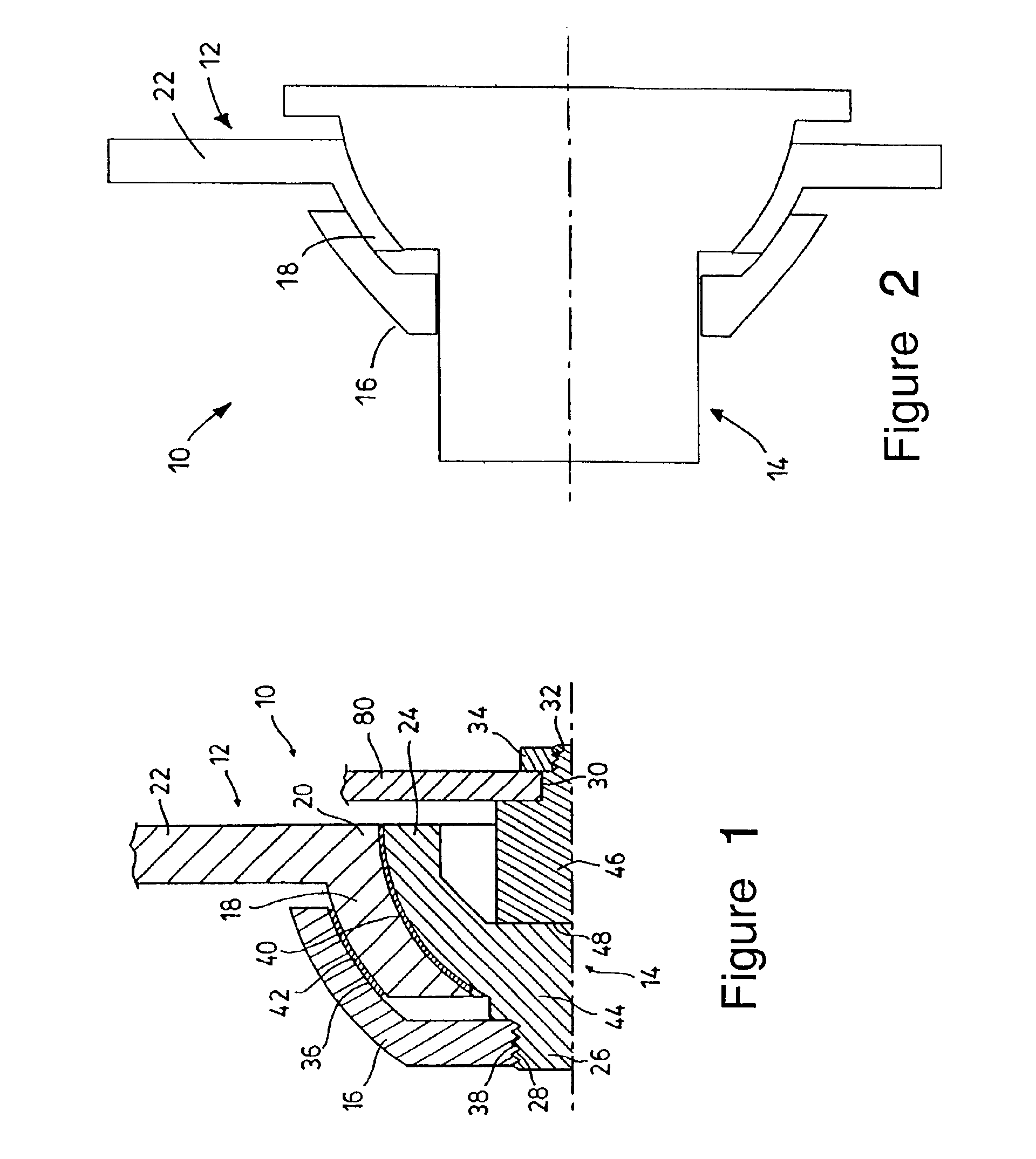
[0050]In the following, the individual parts of the measurement device according to the present invention are described with reference to FIGS. 1 and 2.
[0051]The force transmission element 12 has a spherical zone region / spherical cup region 18, i.e., a region which essentially corresponds to a half sphere having a cut-off cap. An attachment element 22 extends in the radial direction in at least some regions from an equator region 20 of the spherical zone region 18 of the force transmission element 12. The attachment element 22 is preferably implemented in one piece with spherical zone region 18. Attachment element 22 may have the shape of a circular ring which extends around the circumference of the equator region 20 of the spherical zone region 18. Furthermore, the attachment element 22 may instead extend in the radial direction from the spherical zone region 18 in only some regions. It is even conceivable that attachment element 22 is implemented as one or more mounting ribs. The ...
second embodiment
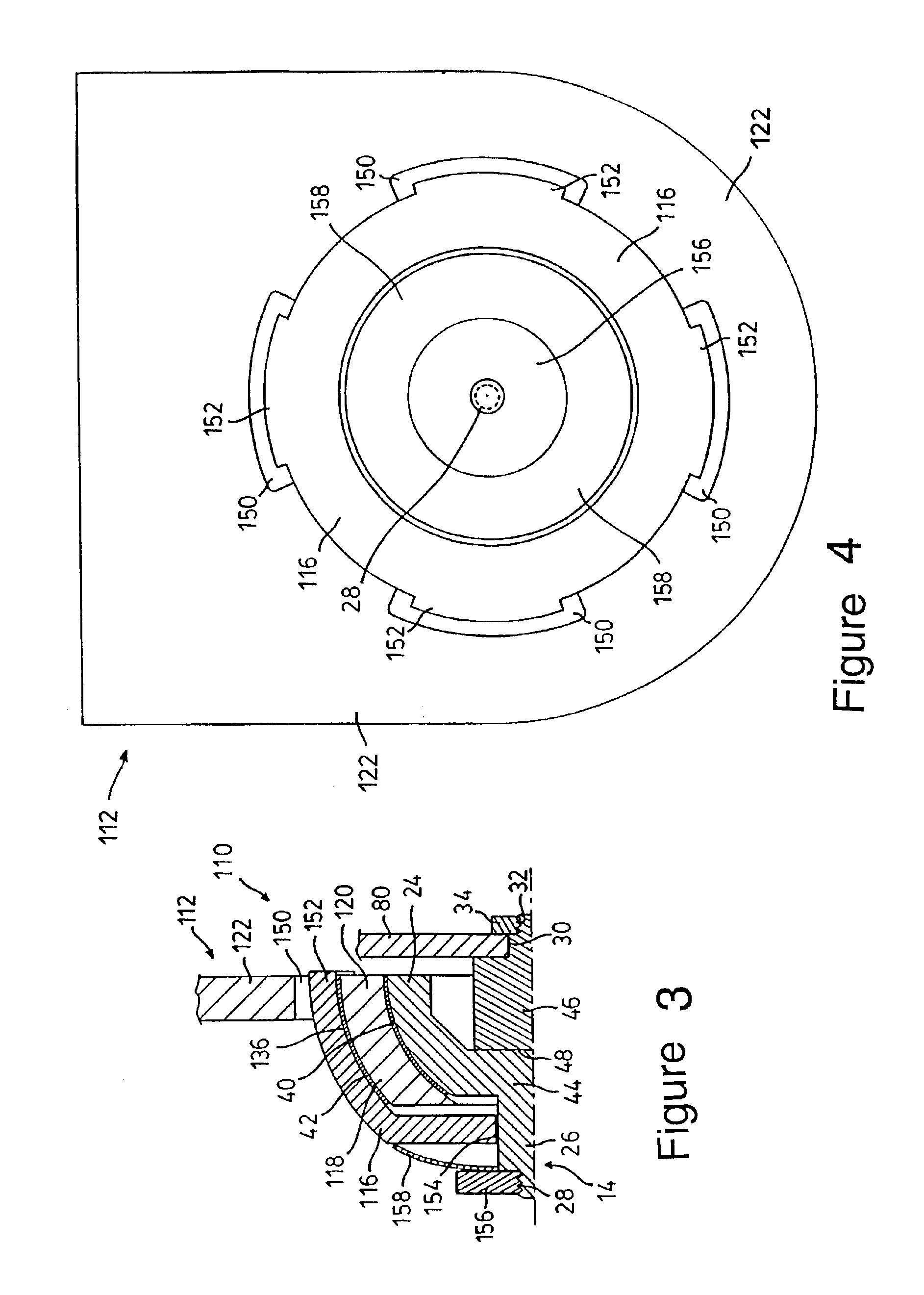
[0060]A measurement device 110 according to the present invention is shown in FIGS. 3 to 7.
[0061]The measurement device 110 according to the second embodiment of the present invention includes elements which are similar or identical to elements of the measurement device 10 according to the first embodiment of the present invention. Such similar or identical elements are indicated with the same reference numbers as in the first embodiment, and a more detailed description thereof will be dispensed with here.
[0062]Measurement device 110 includes a force transmission element 112, a measurement assembly 14, and a union / positioning device 116.
[0063]The force transmission element 112 according to the second embodiment of the present invention includes, like the force transmission element 12 according to the first embodiment of the present invention, a spherical zone region 118, an equator region 120, and an attachment element 122. Recesses 150 are provided in the attachment element 122 acc...
fourth embodiment
[0074]FIG. 11 shows a perspective view of a measurement device 210 and FIG. 12 shows a perspective view of a force transmission element 212 according to the present invention.
[0075]The force transmission element 212 is implemented in the form of a plate, one end of which is connectable to the vehicle seat (not shown). The other end 216 of the force transmission element 212 is preferably rounded and / or semicircular, the radius of the circle corresponding to half the width of the force transmission element 212. A hole 218 is provided in the rounded end 216, in which a rotatably mounted rotating element / circular ring 220 is provided.
[0076]The circular ring is preferably rotatable around an axis A—A, which extends essentially perpendicular to the longitudinal extension of the force transmission element 212. A slip ring 240 is provided in an opening 222 of the circular ring 220, into which a preferably cylindrical measurement assembly 214, which includes a sensor device 246, is inserted....
PUM
| Property | Measurement | Unit |
|---|---|---|
| angle | aaaaa | aaaaa |
| tensile forces | aaaaa | aaaaa |
| pressure forces | aaaaa | aaaaa |
Abstract
Description
Claims
Application Information
 - R&D
- Intellectual Property
- Life Sciences
- Materials
- Tech Scout
- Unparalleled Data Quality
- Higher Quality Content
- 60% Fewer Hallucinations
Browse by: Latest US Patents, China's latest patents, Technical Efficacy Thesaurus, Application Domain, Technology Topic, Popular Technical Reports.
© 2025 PatSnap. All rights reserved.Legal|Privacy policy|Modern Slavery Act Transparency Statement|Sitemap|About US| Contact US: help@patsnap.com


