
Time piece with power generation function

a timepiece and function technology, applied in the field of timepieces, can solve the problems of limited movement, wear and tear, and decrease of demand for digital display watches or clocks

Inactive Publication Date: 2005-08-30
CITIZEN WATCH CO LTD
View PDF16 Cites 18 Cited by
  • Summary
  • Abstract
  • Description
  • Claims
  • Application Information

AI Technical Summary

Problems solved by technology

Therefore the movement is limited and the wear and tear occur with years of use.
However, digital display of time information or calendar information in only a black display on a white background is monotonous in design, lacks an interesting point, and loses its popularity among customers, which results in a decrease of demand of a digital display watch or clock.
A method of shielding a portion of or all of a time-display section on a watch or clock in accordance with circumstances at the time of use or internal condition of the watch or clock has been studied, but the progress can not be said sufficient in terms of making the timepiece thinner and regarding the controllability.
However, the design problems of such a timepiece have not been erased.
Furthermore, in the case of a table clock or a wall clock equipped with a marionette and the like, opening and closing of a screen or a door to show the motion of the doll and the like to viewers are carried out mechanically at present, which limits the movement and also causes a disadvantage of deterioration occuring with years of use.

Method used


Image

  • Time piece with power generation function
  • Time piece with power generation function
  • Time piece with power generation function

Examples


first embodiment

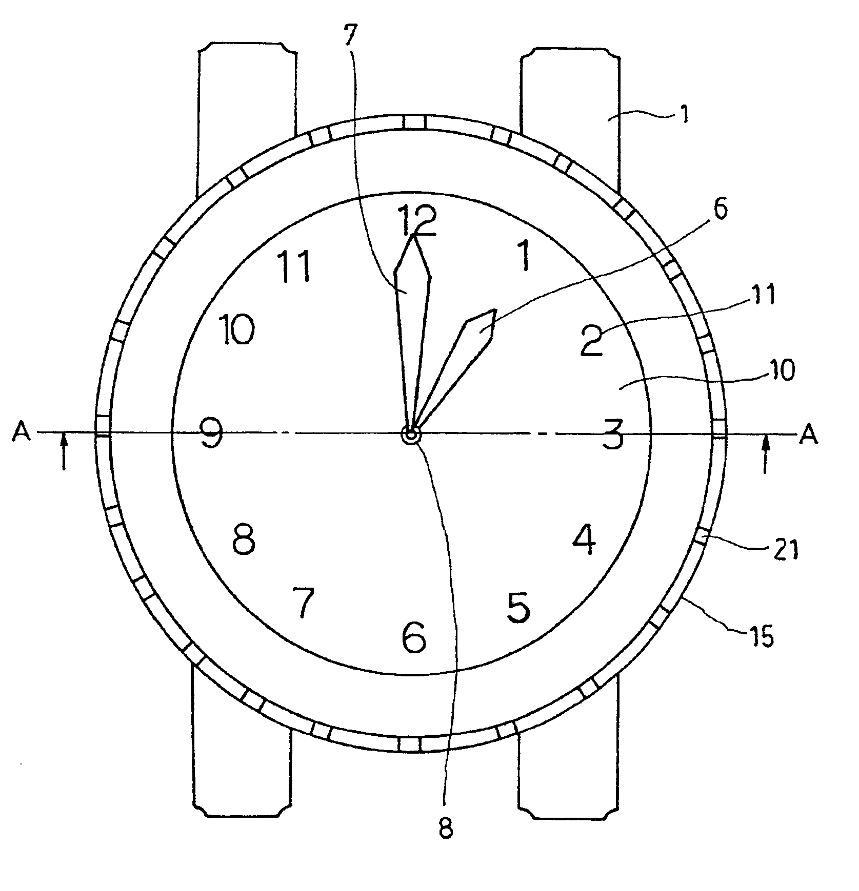
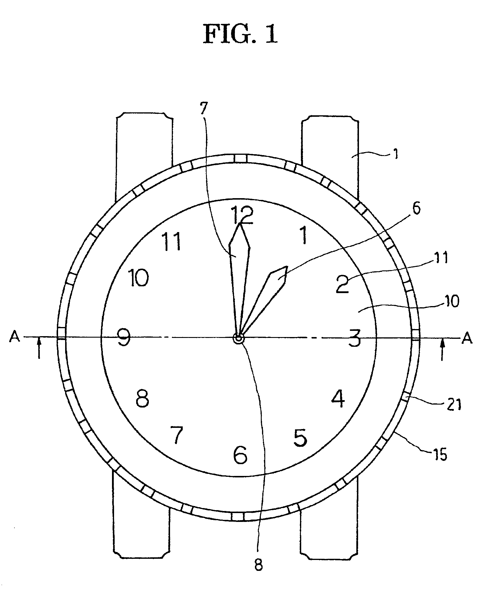
[0048]FIG. 1 is a plane view of a watch showing the first embodiment of the present invention, and FIG. 2 is a schematic sectional view taken along the line A—A in FIG. 1.

[0049]A case 1 is provided with glass 2 and a case back 3, and a time-display section includes a printed circuit board 4 having an electric circuit, and a stepping motor and the like to drive a hand shaft 8, a secondary battery 5, an hour hand 6 and a minute hand 7 which are connected to the hand shaft 8. Incidentally, the hour hand shaft and the minute hand shaft are concentrically inserted into the hands shaft 8.

[0050]A reflection-type polarizing film serving as a first polarizing film 9 is arranged between the hour hand 6 and the printed circuit board 4. On the case back 3 side (back side) of the reflection-type polarizing film 9, provided is the dial 10 on which numerals from “1 to 12” expressing the time are printed near the periphery of a front surface of a translucent ceramic substrate.

[0051]On the back side...

second embodiment

[0068]A second embodiment of the present invention will be explained with reference to FIG. 4 and FIG. 5.

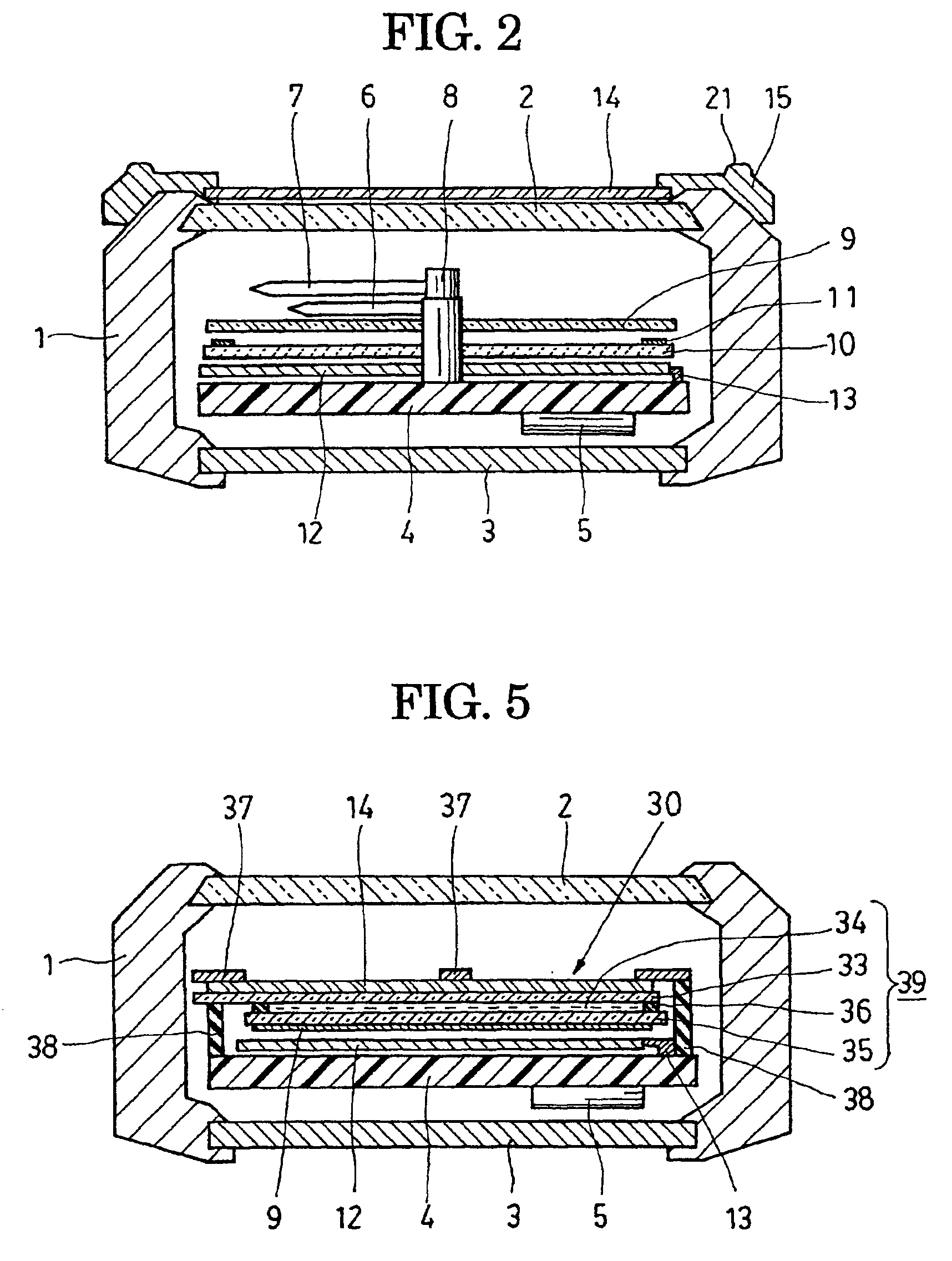
[0069]In the embodiment, a shutter function is performed by the interplay of the first polarizing film 9, the second polarizing film 14, and a liquid crystal cell 39.

[0070]By applying the liquid crystal cell 39, the shutter function can be electrically varied. For the time-display section, a liquid crystal display panel which is the same as that for the shutter function is applied. Consequently, a watch can be made thinner.

[0071]FIG. 4 is a plane view of a watch showing the second embodiment. FIG. 5 is a schematic sectional view taken along the line B—B.

[0072]A liquid crystal display panel used in the embodiment displays much character information to apply to both a time-display section and an optical modulation section, and a matrix-type liquid crystal display panel is adopted to further enrich the shutter function.

[0073]As a polarizing film to form a liquid crystal display pane...

third embodiment

[0088]Next, the third embodiment of the present invention will be explained with reference to FIG. 6 and FIG. 7.

[0089]The formation in the third embodiment will be explained, in which both of the polarizing films that form the liquid crystal display panel 30 are of a reflection-type polarizing film and are used as an optical modulation section, and a solar cell is provided as a power-generating element.

[0090]It is an embodiment in which a shutter function to vary the ratio of a transmission area having a large transmittance to a reflection area having a large reflectance in the liquid crystal display panel using a reflection-type polarizing film in accordance with the intensity of light incident on a solar cell and the magnitude of electricity accumulation amount, is provided, and the amount of power generation of the solar cell is displayed, a danger signal due to decrease of the electricity accumulation amount is issued, and control of an amount of power generation of the solar ce...


PUM


Abstract

A watch unit having a time-displaying section, including a reflection-type polarizing film 14 disposed on an upper portion or a lower portion of the time-displaying section or a portion comprising a part of the time-displaying section, an optical modulation section which varies the ratio of a transmission axis to a reflection axis of the reflection-type polarizing film 14, and a shutter function to shield a portion of or all of the watch unit having the time-display section by varying the reflection intensity and the transmission intensity in relation to the light incident direction using the reflection-type polarinzing film 14 and the optical modulation section, to enhance the appearance and to improve the versatility of the watch unit.

Description

[0001]This application is a continuation of prior application Ser. No. 09 / 254,842 filed Mar. 15, 1999 which is a 371 of PCT / JP98 / 0325 filed on Jul. 21, 1998, and which is hereby incorporated by reference.TECHNICAL FIELD[0002]The present invention relates to a timepiece (watch and clock) which displays time information such as hours, minutes, and seconds, calendar information such as date, day-of-the week, month, and year in digital form, using a liquid crystal panel, and time information using an hour hand, a minute hand, a second hand, and the like in an analog fashion.BACKGROUND ART[0003]A timepiece which displays time information such as hours, minutes, and seconds, and calendar information such as date, day-of-the week, month, and year using a liquid crystal display panel has been widely used in a wrist watch or a table clock which is equipped with a crystal oscillator circuit.[0004]When time information or calendar information is to be displayed in digital form using the liquid...

Claims


Application Information

Patent Timeline
IPC IPC(8): G02F1/13G02F1/1347G04G9/00G02F1/1335
CPCG02F1/13471G04G9/0035G04G9/0082G02F1/133536G02F2001/133545G02F1/133545G04G9/00
Inventor SEKIGUCHI, KANETAKAIDE, MASAFUMIAKIYAMA, TAKASHIKIKUCHI, MASAMIAKIBA, YUICHINAKAGAWA, KOJIHOSHINO, KOICHITOIDA, TAKASHI
Owner CITIZEN WATCH CO LTD
Learn More