Apparatus and methods for optically monitoring thickness

a technology of optical monitoring and thickness, applied in the field of surface measurement, can solve the problems of undesirable surface contact solutions, adverse effects on the quality and repeatability of stamped sheet metal components, and disadvantages of techniques

Inactive Publication Date: 2005-08-30
MASSACHUSETTS INST OF TECH
View PDF59 Cites 43 Cited by
  • Summary
  • Abstract
  • Description
  • Claims
  • Application Information

AI Technical Summary

Benefits of technology

[0010]The apparatus further includes a control system locating the first and second fringe patterns to second locations on the first and second surfaces, respectively, the first and second detectors generating third and fourth signals, respectively in response to the first and second fringe patterns at the second locations, the processor is adapted to calculate variations in the thickness of the object in response to the first, second, third and fourth signals. In one embodiment, the first and second sources are laser sources. In another embodiment, the first and second sources are the same source. In yet another embodiment, the first and second sources are generated from a single source. In still another embodiment, the first and second sources include two subsources. In another embodiment, the two subsources are coherent with respect to each other. In yet another embodiment, the first and second sources are broadband sources. In another embodiment, the first and second sources are coherent with respect to each other. In one embodiment, the first and second fringe patterns are generated by interfering radiation from at least two sources. In another embodiment, the rad

Problems solved by technology

Thickness control is critical, for example, in the production of sheet-metal stock where variations in thickness adversely affect the quality and repeatability of stamped sheet metal components.
However, these surface contact solutions are undesirable since they involve the invasive contacting of the surface and they generally require too much time to make a measurement.
These techniques have disadvantages, however.
These techniques are also impractical for very thick materials because of the high losses and the difficulty of achieving an adequate signal to noise ratio in the m

Method used


Image

  • Apparatus and methods for optically monitoring thickness
  • Apparatus and methods for optically monitoring thickness
  • Apparatus and methods for optically monitoring thickness

Examples


Embodiment Construction

[0028]While describing the embodiment of the invention, reference will be made to “sources” and “sources of radiation.” These terms are meant to refer to any source of radiation, including highly localized sources of radiation.

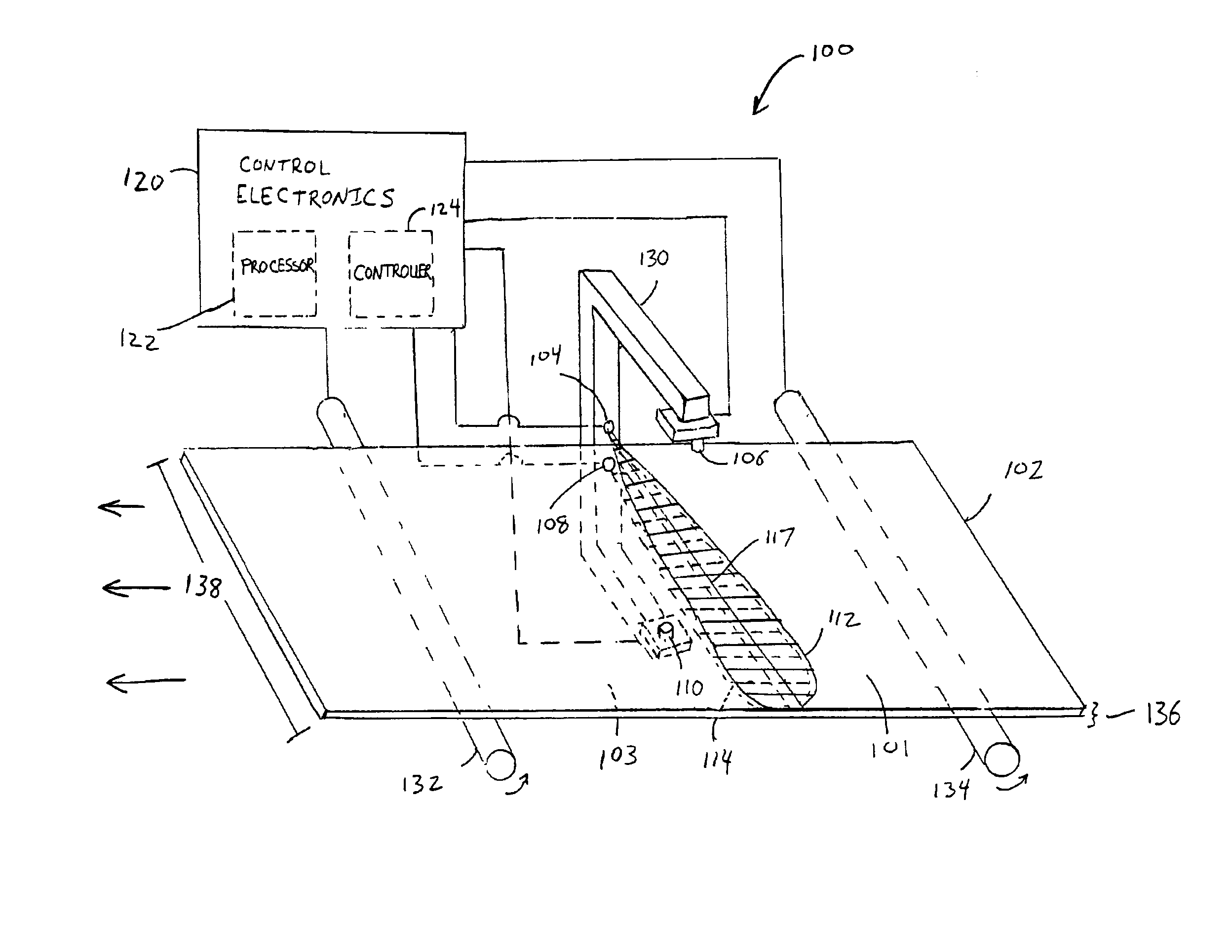
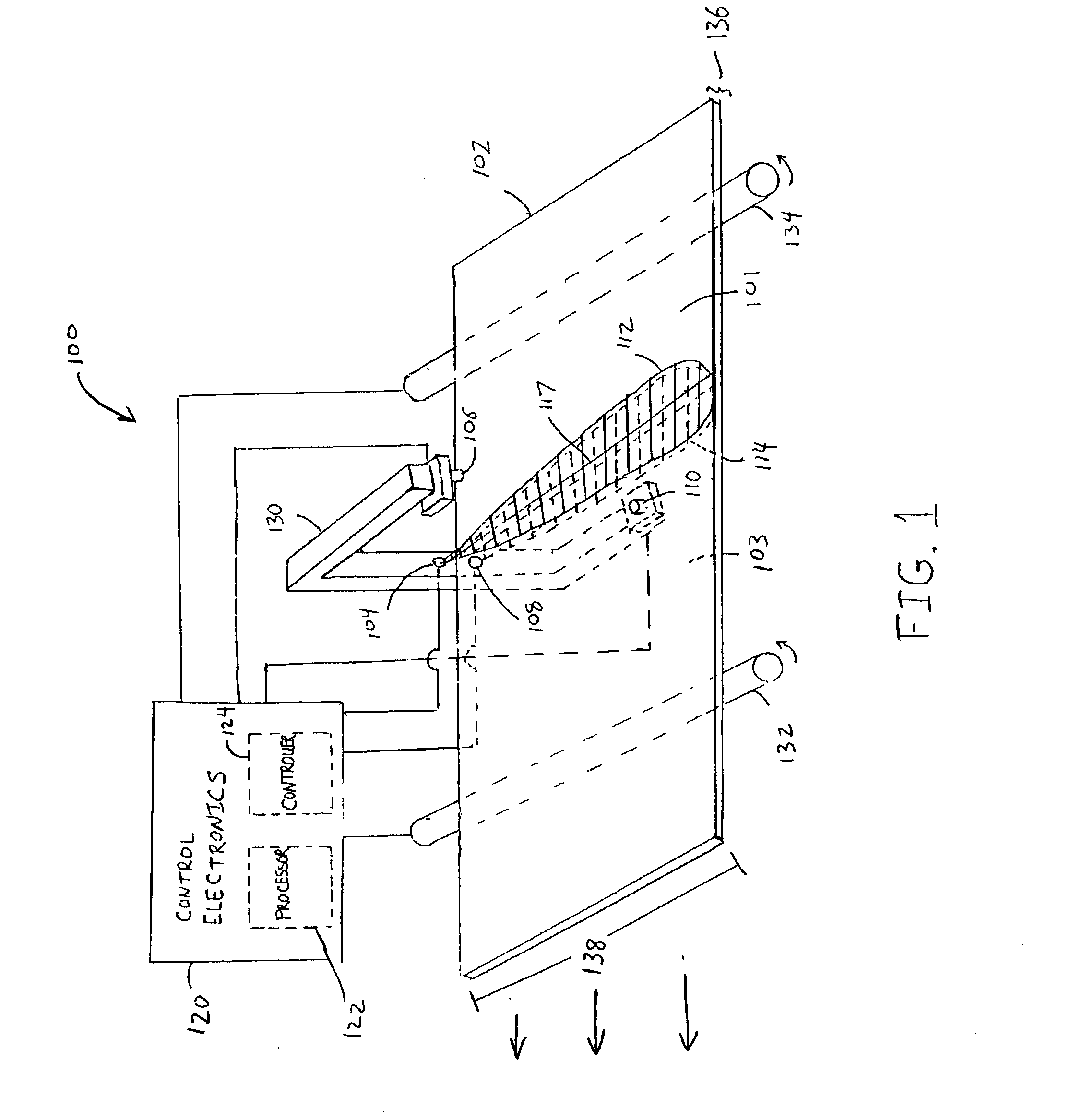
[0029]A preferred embodiment of the invention is illustrated in FIG. 1. The system 100 is shown as monitoring the thickness of a sheet of material 102 passing through the system 100. In alternate embodiments, the material 102 is steel, plastic, rubber, lumber, paper, or the like. Generally the material 102 is produced by high speed extrusion, rolling, drawing, casting, sawing, or other similar techniques in which the output is carried along a conveyer-type apparatus. The system 100 comprises a first source of radiation 104 and a first detector 106. The system further comprises a second source of radiation 108 and a second detector 110. The first source 104 is adapted to project a first fringe pattern 112 onto a first surface 101 of the sheet of material 102. T...


PUM


Abstract

In one aspect, the invention relates to an apparatus for monitoring thickness variations of an object having first and second opposing surfaces. The apparatus includes a first source positioned to project a first fringe pattern at a first location on the first surface and a second source positioned to project a second fringe pattern at a first location on the second surface. The apparatus further includes a first detector positioned to detect the first fringe pattern at the first location on the first surface, the first detector generating a first signal in response to the first fringe pattern at the first location. The apparatus also includes a second detector positioned to detect the second fringe pattern at the first location on the second surface, the second detector generating a second signal in response to the second fringe pattern at the first location. The apparatus further includes a processor adapted to calculate variations in the thickness of the object in response to the first and the second signals.

Description

CROSS-REFERENCE TO RELATED APPLICATIONS[0001]This application claims the benefits of provisional U.S. patent application Ser. No. 60 / 302,508 filed on Jun. 29, 2001 the disclosures of which are hereby incorporated herein by reference in their entirety.GOVERNMENT SUPPORT[0002]This invention was made with government support under Federal Contract No. F19628-95-L-002, awarded by the United States Air Force. The Government may have certain rights in the invention.FIELD OF THE INVENTION[0003]The invention relates to the field of surface measurement and, more specifically, to the field of non-contact thickness and flatness measurement.BACKGROUND OF THE INVENTION[0004]In many manufacturing processes, it is necessary to make thickness measurements. For example, thickness measurements are used to control the thickness of various manufactured sheet materials. In many cases it is desirable to monitor thickness and provide real-time feedback to the fabrication equipment. Thickness control is cri...

Claims


Application Information

Patent Timeline
IPC IPC(8): G01B11/06G01B11/30
CPCG01B11/06G01B11/0691G01B11/306
Inventor SHIRLEY, LYLE
Owner MASSACHUSETTS INST OF TECH
Why Eureka
Try Eureka