Fuel control mechanism and associated method of use

a technology of fuel control mechanism and associated method, which is applied in the direction of combustion control, combustion types, lighting and heating apparatus, etc., can solve the problems of premature re-establishment of gas flow

a technology of fuel control mechanism and associated method, which is applied in the direction of combustion control, combustion types, lighting and heating apparatus, etc., can solve the problems of premature re-establishment of gas flow

US6938634B2Active Publication Date: 2005-09-06ROBERTSHAW CONTROLS CO

Image

  • Fuel control mechanism and associated method of use
  • Fuel control mechanism and associated method of use
  • Fuel control mechanism and associated method of use

Examples


Embodiment Construction

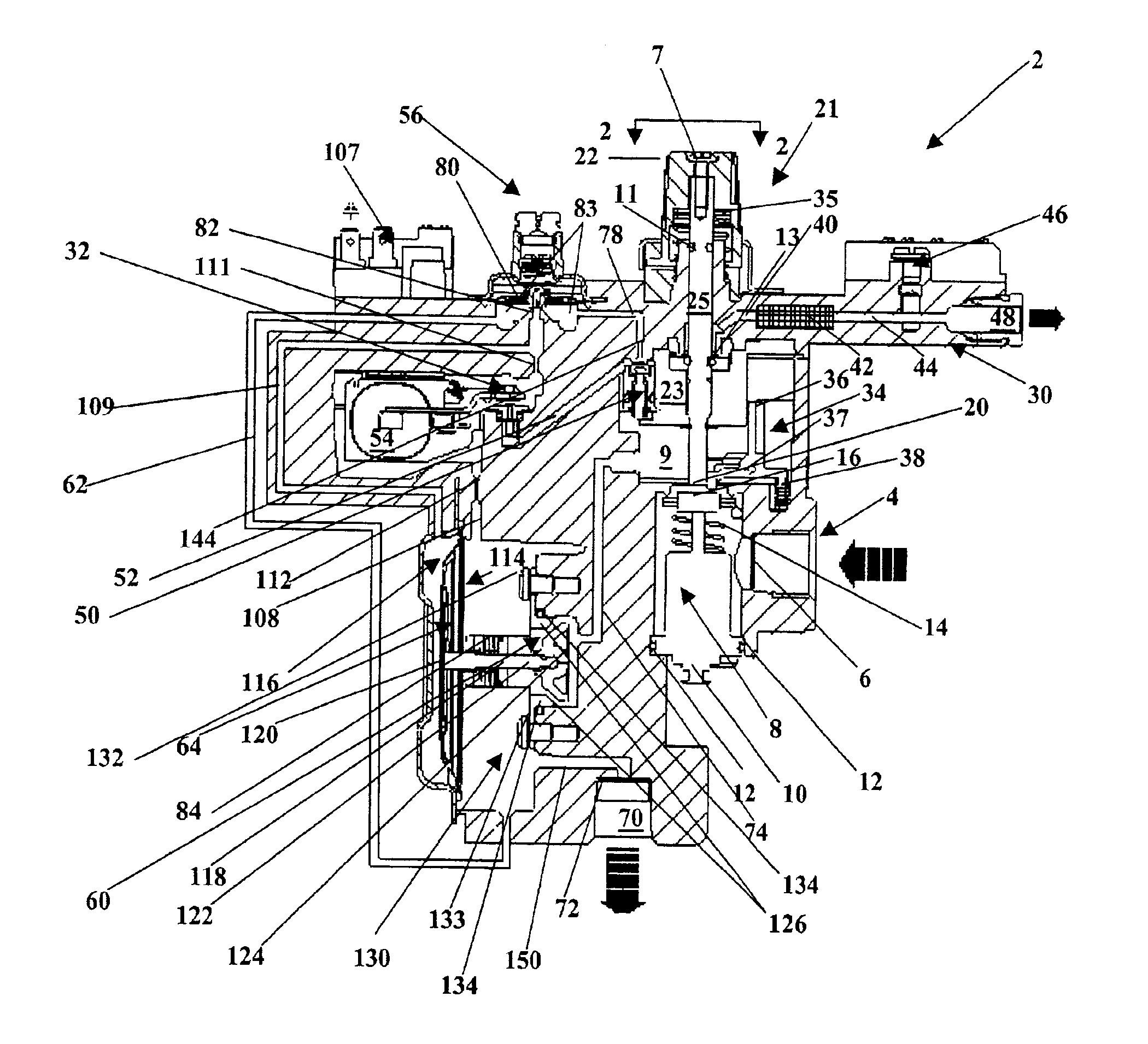
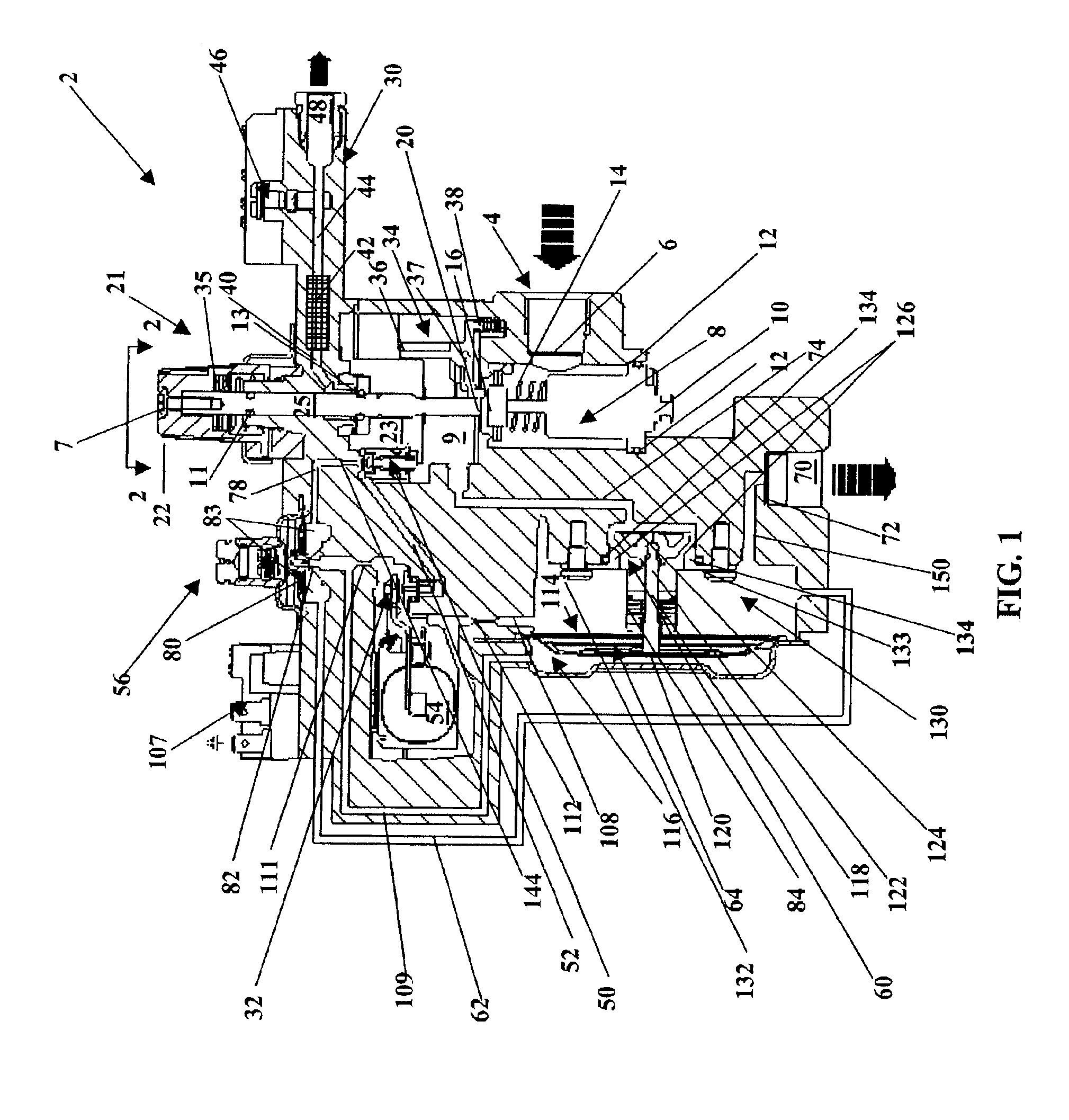
[0018]In the following detailed description, numerous specific details are set forth in order to provide a thorough understanding of the invention. However, it will be understood by those skilled in the art that the present invention may be practiced without these specific details. In other instances, well-known methods, procedures and components have not been described in detail so as to obscure the present invention. For example, the invention can be applied to virtually any type of gas-powered device that can be powered by natural gas and liquefied petroleum. Therefore, this invention can be applied to virtually any type of gas appliance including, but not limited to, furnaces, heaters, fireplaces, and so forth. In addition, this invention may be applied to an engine. The fuel is preferably, but not necessarily, gas. Illustrative, but nonlimiting examples of the types of gas utilized with the present invention include natural gas, manufactured gas and liquefied petroleum, e.g., l...


PUM


Abstract

A control device for regulating delivery of fuel and an associated method of use is disclosed. The control device includes an inlet, an electromagnetic safety valve, having a thermocouple connection, a control valve, wherein the electromagnetic safety valve selectively allows fuel to flow from the inlet to the control valve through the electromagnetic safety valve when the thermocouple connection is heated, an actuator valve, a main valve having a pressure responsive device, having a first side and a second side and including an outlet chamber, a regulator valve having a sensing port and an outlet. There is an adjustment mechanism associated with the control valve that can also direct fuel into a pilot assembly.

Description

BACKGROUND OF THE INVENTION[0001]In the past, there has been a desire to regulate the pressure rate of fuel, e.g., gas, for fuel powered devices including, but not limited to, furnaces, heaters, fireplaces, engines, and so forth. One major problem with currently available devices that regulate gas flow is the ability to immediately stop the flow of gas when desired and to prevent any build-up of gas within the device. It is important that this function is accomplished automatically especially during operating anomalies or a power failure. Another problem is that there can be a premature re-establishment of gas flow. Moreover, the ability to provide a consistent and quality output of fuel, e.g., gas, will enhance the performance and fuel efficiency of any fuel powered device that is utilized.[0002]Another problem is that a majority of these devices are directed to regulating a specific type of fuel at one specific pressure. For example, two types of common fluids used as fuels includ...

Claims


Application Information

Patent Timeline
06 Sep 2005
Publication
US6938634B2
IPC
F02M21/02; F23K5/00; F23N1/00; F23N5/02; F23N5/10
CPC
F23K5/007; F23N1/005; F02M21/0239; F02M21/0242; F02D19/027; F02M21/0233; F23N5/10; F23N2035/14
Inventors
DEWEY, JR., ROBERT GORDON