Electrical rough-in box for low voltage transformer

a low-voltage transformer and rough-in box technology, which is applied in the direction of transformer/react mounting/support/suspension, electrical apparatus casing/cabinet/drawer, coupling device connection, etc., can solve the problems of requiring significantly more electrical wire and electrician time, and not allowing the installation of transformers in attics or non-accessible locations, etc., to reduce the amount of an electrician's time.

Inactive Publication Date: 2005-09-06
HEATH & CO LTD
View PDF34 Cites 76 Cited by
  • Summary
  • Abstract
  • Description
  • Claims
  • Application Information

AI Technical Summary

Benefits of technology

The present invention is an electrical rough-in box for a low voltage transformer that solves problems and provides better access for electricians. This reduces the time and cost for low voltage applications.

Problems solved by technology

The technical problem addressed in this patent text is the difficulty and expense of installing a door bell system due to the need for a low voltage transformer to step down the standard household current to a lower voltage for the chime mechanism. The current method of mounting the transformer in an out-of-the-way place, such as the closet or main electrical breaker box, can be inconvenient for the homeowner and require more electrical wire and electrician time to complete the circuit. Additionally, the need for the push button switch, chime mechanism, and transformer to be located close to each other in practice makes the installation more complicated, time-consuming, and expensive than necessary.

Method used


Image

  • Electrical rough-in box for low voltage transformer
  • Electrical rough-in box for low voltage transformer
  • Electrical rough-in box for low voltage transformer

Examples


Embodiment Construction

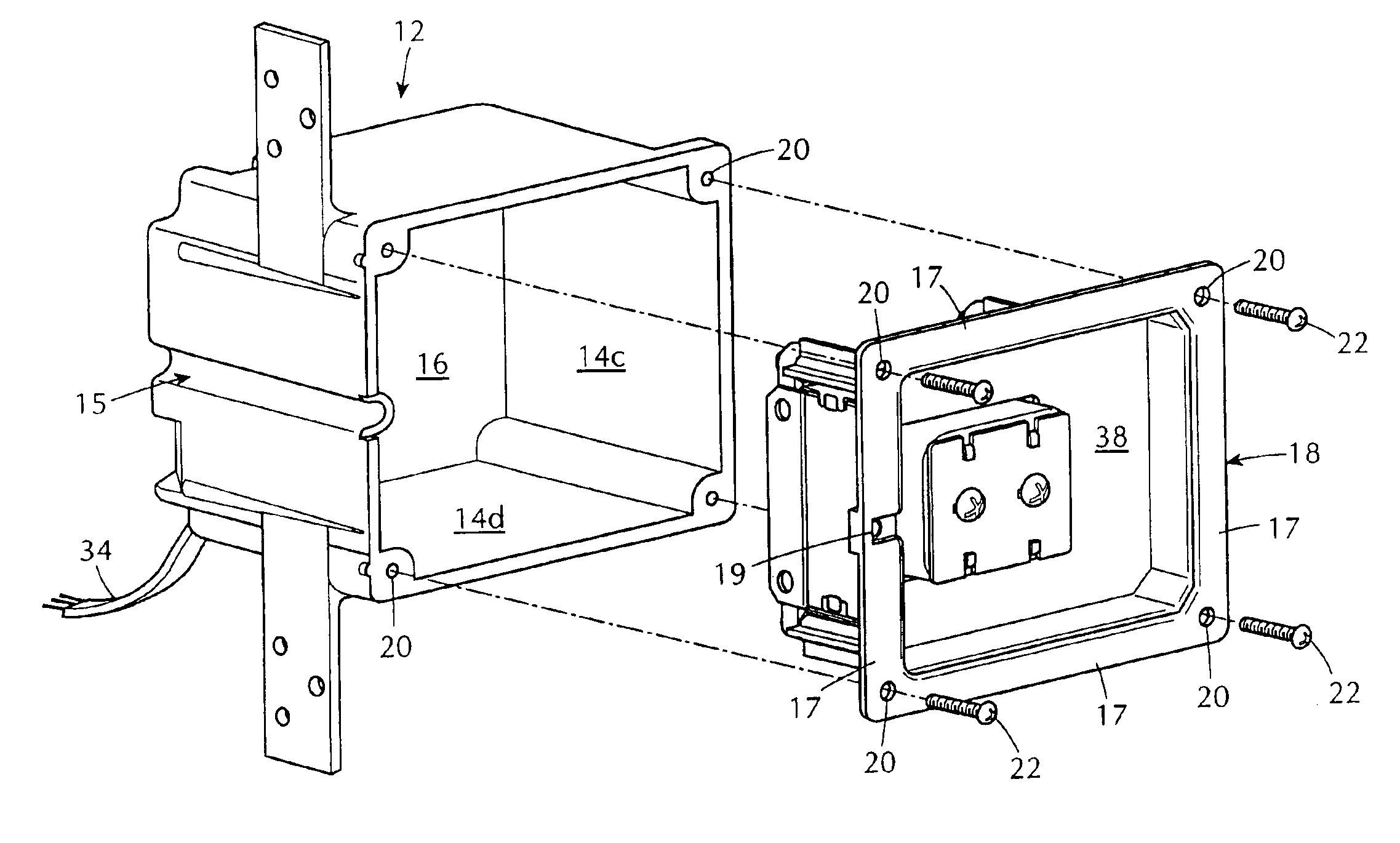
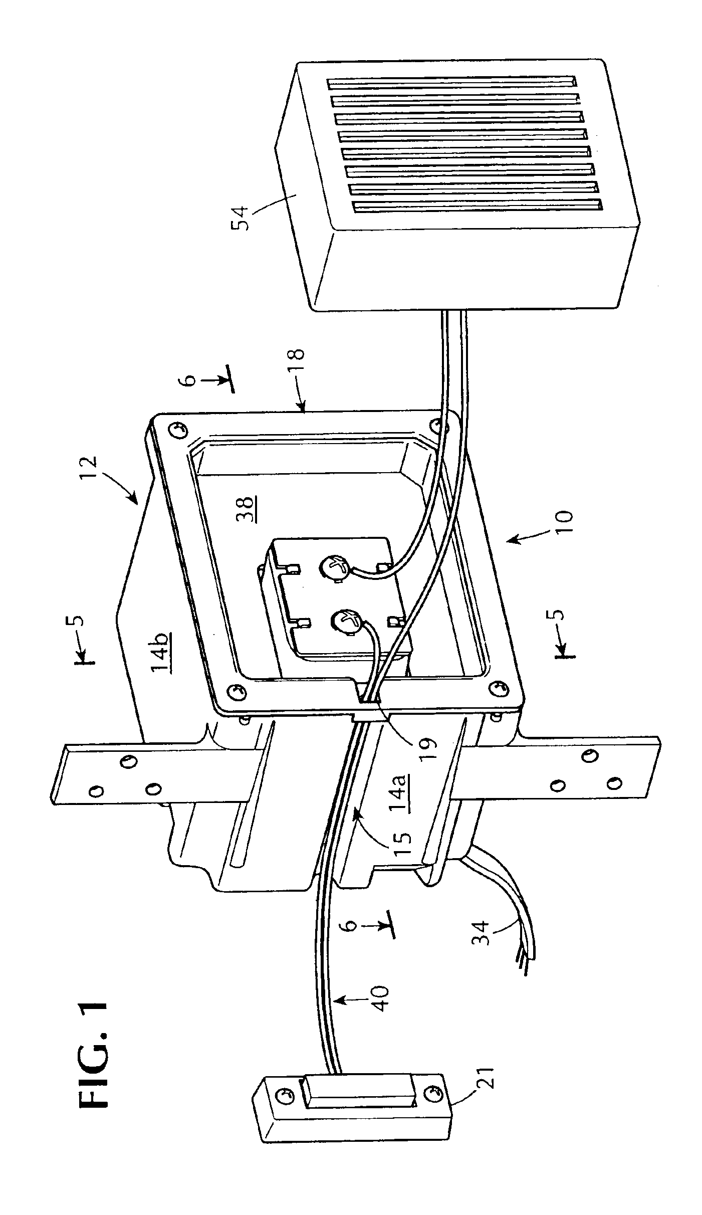
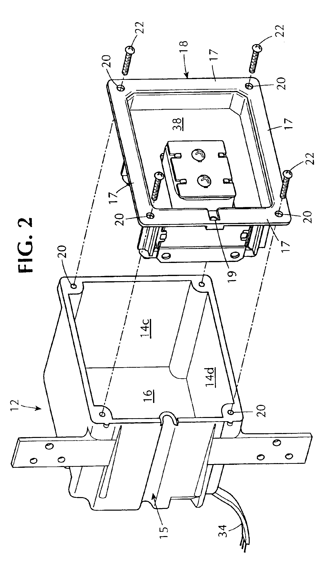
[0021]Referring now to the drawings there is shown in FIG. 1 an electrical rough-in box for a low voltage transformer. The box 10 preferably includes a generally square-shaped cover 18 and generally square-shaped body 12 having four sidewalls 14a, 14b, 14c, 14d and a bottom wall 16 (FIG. 2). The bottom wall 16 is in contact with and connected to each of the sidewalls. It will be understood by those of ordinary skill in the art that the shape of the body 12 and cover 18 need not be generally square but may, alternatively, be generally rectangular, triangular, circular or of other geometric shape.

[0022]The box 10 may be constructed of metal or plastic. Preferably, the box 10 is formed from moldable plastic, such as polycarbonate or the like, which makes the box easy to manufacture using standard injection molding techniques. Sidewalls 14a, 14b, 14c, 14d and bottom wall 16 are preferably molded together to form a one piece body 12. One or more of sidewalls 14a, 14b, 14c, 14d preferably...


PUM


Abstract

An electrical rough-in box for a low voltage transformer is provided. The box has a removable cover with a low voltage transformer mounted there through. The removable cover contains a recessed portion for accommodating low voltage wiring. A sidewall of the box contains a channel for low voltage wiring, thus permitting flush mounting of the box against a wall stud.

Description


Claims


Application Information

Patent Timeline
Owner HEATH & CO LTD
Why Eureka
Try Eureka