Faceted expansion relief perforating device

a perforating device and expansion relief technology, applied in the direction of fluid removal, explosive charges, borehole/well accessories, etc., can solve the problems of retrieval problems, significant distortion of hollow steel carriers, retrieval problems, etc., and achieve the effect of less steel and stronger structural integrity

Inactive Publication Date: 2005-09-13
MAULDIN SIDNEY WAYNE
View PDF10 Cites 12 Cited by
  • Summary
  • Abstract
  • Description
  • Claims
  • Application Information

AI Technical Summary

Benefits of technology

[0015]The present invention is a well perforating device and method of manufacture to make a plurality of connected faceted cuts in the outer surface of the body member at the level of the perforating charge covering the greater part of the circumference. These faceted cuts serve to control the swelling and outer deformation of the perforating gun, after detonation, in a manner such that less steel is removed resulting in a stronger structural integrity. The stronger structural integrity helps to achieve all of the other aspects necessary for a perforating gun and allow this design to use standard steel.

Problems solved by technology

This is similar to the previously discussed casing gun with the addition of larger charges that will cause significant distortion to the hollow steel carrier.
The distortion can be sufficient as to cause retrieval problems.
The smaller diameter is not as capable of absorbing the explosive charge and the outer diameter of the hollow carrier is distorted.
Excessive distortion can result costly remedial measures and can even run the risk of making the well junked and abandoned.

Method used


Image

  • Faceted expansion relief perforating device
  • Faceted expansion relief perforating device
  • Faceted expansion relief perforating device

Examples


example

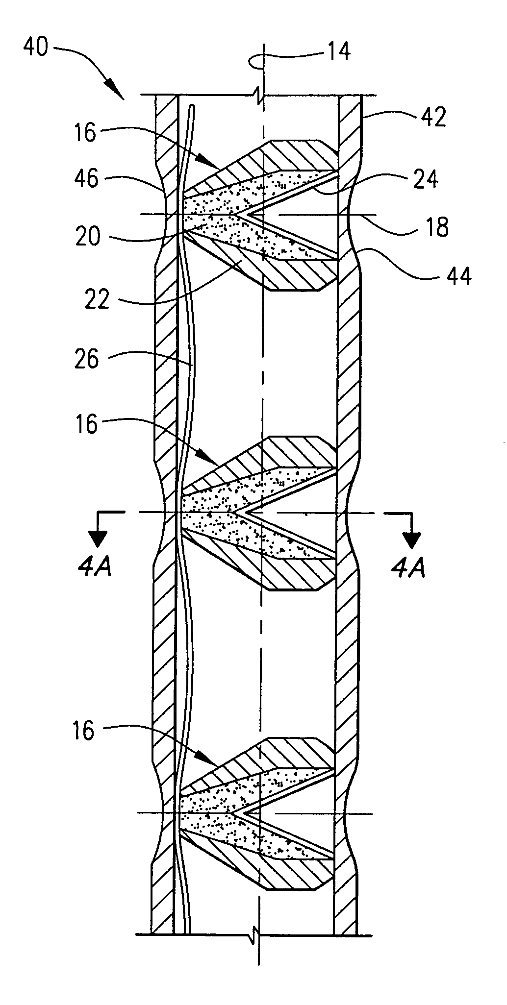
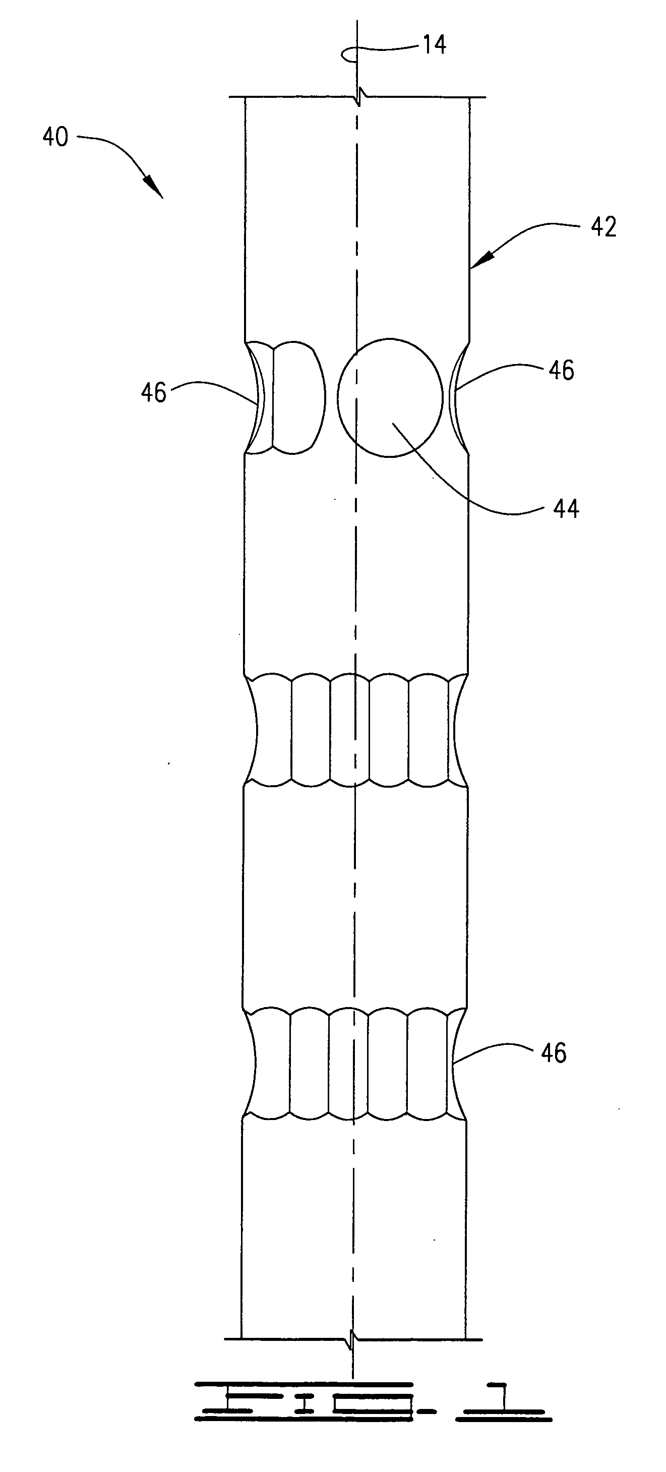
[0042]The present invention 40 was tested by constructing a perforating device as described in the Detailed Description of the Invention and detonating it under the following conditions. The body member 42 was constructed with industry standard heat treated steel with an outer diameter of 2.030 inches, a yield strength of 145,000 to 160,000 psi and an average impact strength of 51.6 ft-lbs (Charpy-V full size). The body member 42 was hydrostatically tested to 22,500 psi with no failure. A variety of industry standard 7 gram perforating charges 16 of different manufacturers were used with a shot density of 6 shots per foot. When detonated at 2500 psi, the maximum swelling was 2.055 inches. When detonated covered by water at atmospheric pressure, the maximum swelling was 2.086 inches. These figures compare with typical normal swelling of 2.125 for 4 shots per foot and 2.170 for 6 shots per foot.


PUM


Abstract

The present invention is an improvement in the design of a perforating gun to perforate the casing in oil and gas wells. Perforating guns have a cylindrical body member with explosive charges at specified intervals designed to shoot outwardly through the body member, the well casing, cement sheath, and into the rock formation. Continuous faceted cuts in the vessel covering the greater part of the circumference, at the level of the charge, serve to reduce the outward distortion of the body member beyond the original diameter of the body member. Reducing the distortion serves to insure that the perforating gun can be removed from the well after the explosive charges have fired.

Description

CROSS-REFERENCE TO RELATED APPLICATIONS[0001]Not ApplicableSTATEMENT REGARDING FEDERALLY SPONSORED RESEARCH OR DEVELOPMENT[0002]Not ApplicableREFERENCE TO A MICROFICHE APPENDIX[0003]Not ApplicableBACKGROUND OF THE INVENTION[0004]The invention relates generally to an improvement in the design of an oil and gas well perforating device. The improvement applies to a type of perforating device that is typically lowered into the well through the casing or tubing in the well to a position where the explosive charges are detonated at the desired depth. The improvement is a method of decreasing the distortion of the device after detonation to ensure that it can be pulled back out of the well.[0005]After an oil or gas well is drilled, steel casing is lowered into the well and cemented to the adjoining rock formations. Typically, perforations are needed to allow the oil or gas from the desired rock formation to be able to flow into the casing and then out of the well. The perforations are made...

Claims


Application Information

Patent Timeline
Patent Type & Authority Patents(United States)
IPC IPC(8): E21B43/117E21B43/119E21B43/11
CPCE21B43/117E21B43/119
Inventor MAULDIN, SIDNEY WAYNE
Owner MAULDIN SIDNEY WAYNE
Why Eureka
Try Eureka