
A buoy device

a buoy and device technology, applied in the field of buoy devices, can solve the problems of adding weight, increasing fabrication time, and increasing manpower and manpower (and hence cost) required to construct, transport and install known buoy devices, and achieve the effect of less steel

Active Publication Date: 2019-04-18
CAN SYST AS
View PDF3 Cites 0 Cited by
  • Summary
  • Abstract
  • Description
  • Claims
  • Application Information

AI Technical Summary

Benefits of technology

The invention is a buoy device that is lighter and faster to make than existing buoys. It has advantages in terms of being easier to assemble and leakproof. It also reduces the amount of lifting required and can be assembled anywhere.

Problems solved by technology

This adds weight and fabrication time.
Time, equipment, and manpower (and hence cost) required to construct, transport and install known buoy devices are therefore considerable.

Method used


Image

  • A buoy device
  • A buoy device
  • A buoy device

Examples


Embodiment Construction

[0050]The following description may use terms such as “horizontal”, “vertical”, “lateral”, “back and forth”, “up and down”, “upper”, “lower”, “upwards”, “downwards”, “inner”, “outer”, “forward”, “rear”, etc. These terms generally refer to the views and orientations as shown in the drawings and that are associated with a normal use of the invention. The terms are used for the reader's convenience only and shall not be limiting.

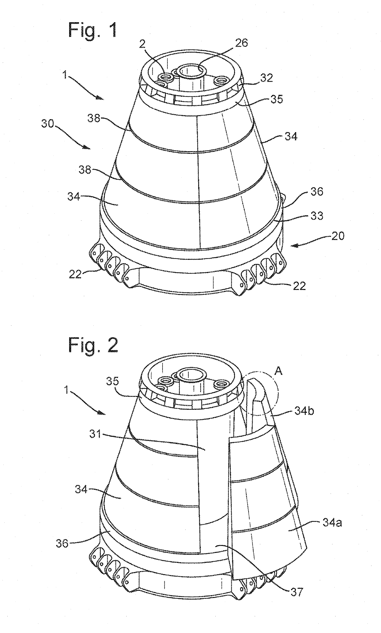
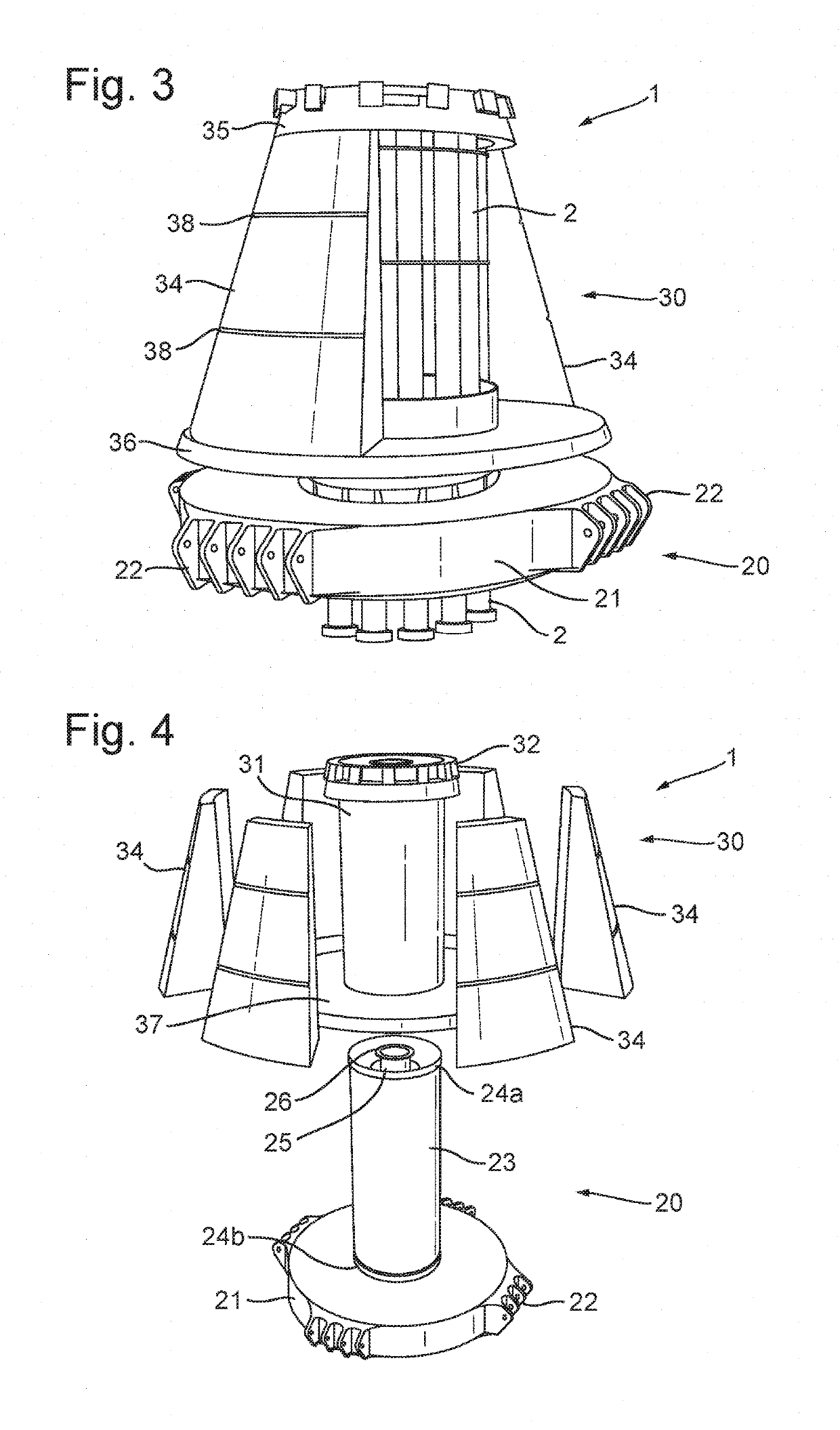
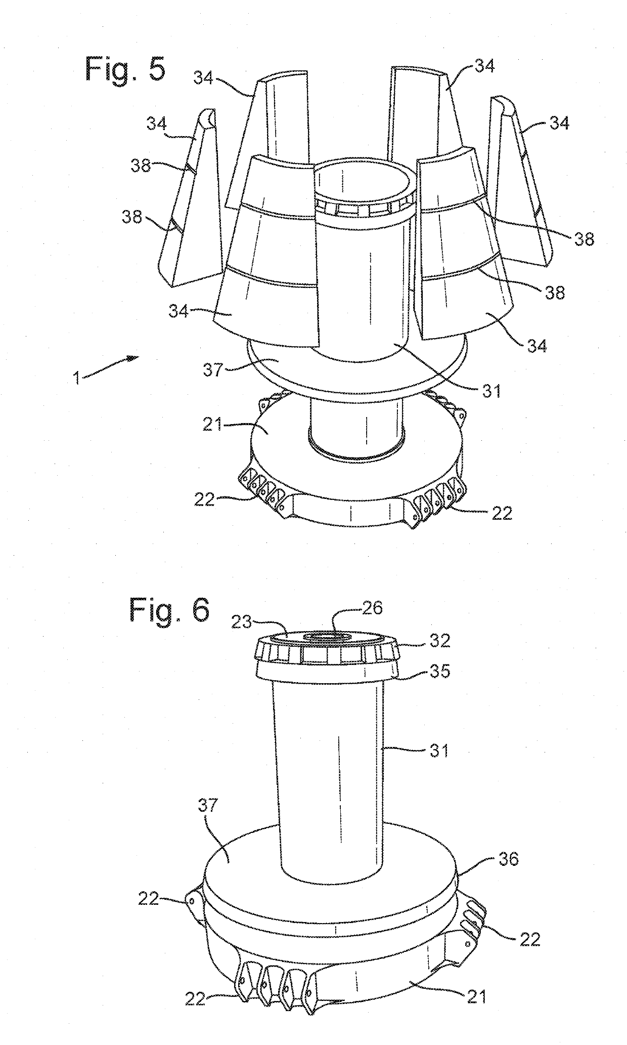
[0051]Referring initially to FIG. 4 and FIG. 5, the invented buoy device comprises in one embodiment a turret buoy 1 having a turret 20 and a buoyant body 30. The turret 20 comprises a base portion 21, having a plurality of mooring connectors 22 to which mooring lines or chains (not shown) may be attached. The figure shows a base portion having four groups of mooring connectors 22 arranged at regular intervals around the base portion perimeter, each group consisting of five mooring connectors. It should be understood that more or fewer mooring connectors and co...


PUM


Abstract

A buoy device includes a first part having a first support structure and a second part having a buoyant body and a second support structure. The first and second support structures are connectable to form a rotatable connection between the first part and the second part. The buoyant body further includes one or more buoyancy elements releasably arranged on the second part. The buoy device may be a turret buoy, a CALM turret buoy, or a CALM turntable buoy.

Description

FIELD OF THE INVENTION[0001]The invention concerns a buoy device as set out by the preamble of claim 1, and methods of assembling the buoy device, as set out by the preamble of claims 12 and 13.BACKGROUND OF THE INVENTION[0002]In the production of hydrocarbons from offshore wells in deep seas, so-called Floating Production, Storage and Offloading (FPSO) ships, or similar concepts, are widely used. Ships of this type often rely on disconnectable turret buoy systems, both for mooring and as a means for connecting to the hydrocarbon risers. In general terms, the known turret buoy systems comprise a turret and a buoyant body, where the buoyant body is configured for connection to a receptacle in the vessel (e.g. the FPSO), and the turret is rotatably arranged inside the buoyant body via bearings (slewing bearings or sliding bearings). The turret has connectors for mooring lines and support hang-off structures for risers. Other variants, employing basically the same principle, are known ...

Claims


Application Information

Patent Timeline
Patent Type & Authority Applications(United States)
IPC IPC(8): B63B22/02B63B3/08
CPCB63B22/02B63B3/08B63B22/021B63B22/026B63B21/507B63B2022/028
Inventor BECH, ARILDSTORVOLL, EIRIK
Owner CAN SYST AS
Learn More