Convertible control device capable of regulating fluid pressure for multiple fluid types and associated method of use

a technology of fluid pressure and control device, which is applied in the direction of fluid pressure control, combustion types, instruments, etc., can solve the problems of not always knowing what type of fuel will be available, inability to adapt to the changing conditions of fluid pressure,

Active Publication Date: 2005-09-13
ROBERTSHAW CONTROLS CO
View PDF23 Cites 38 Cited by
  • Summary
  • Abstract
  • Description
  • Claims
  • Application Information

AI Technical Summary

Benefits of technology

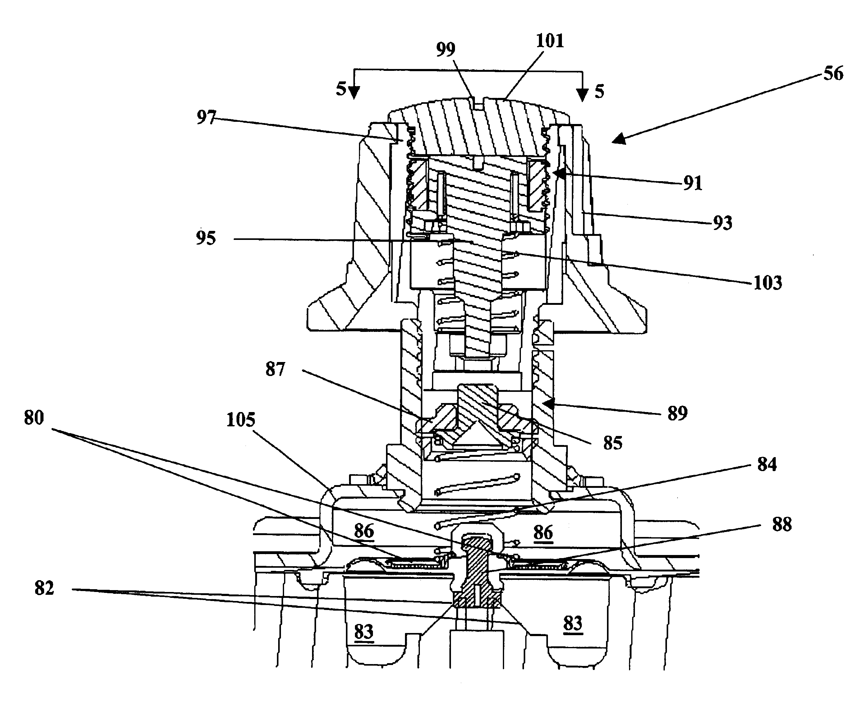
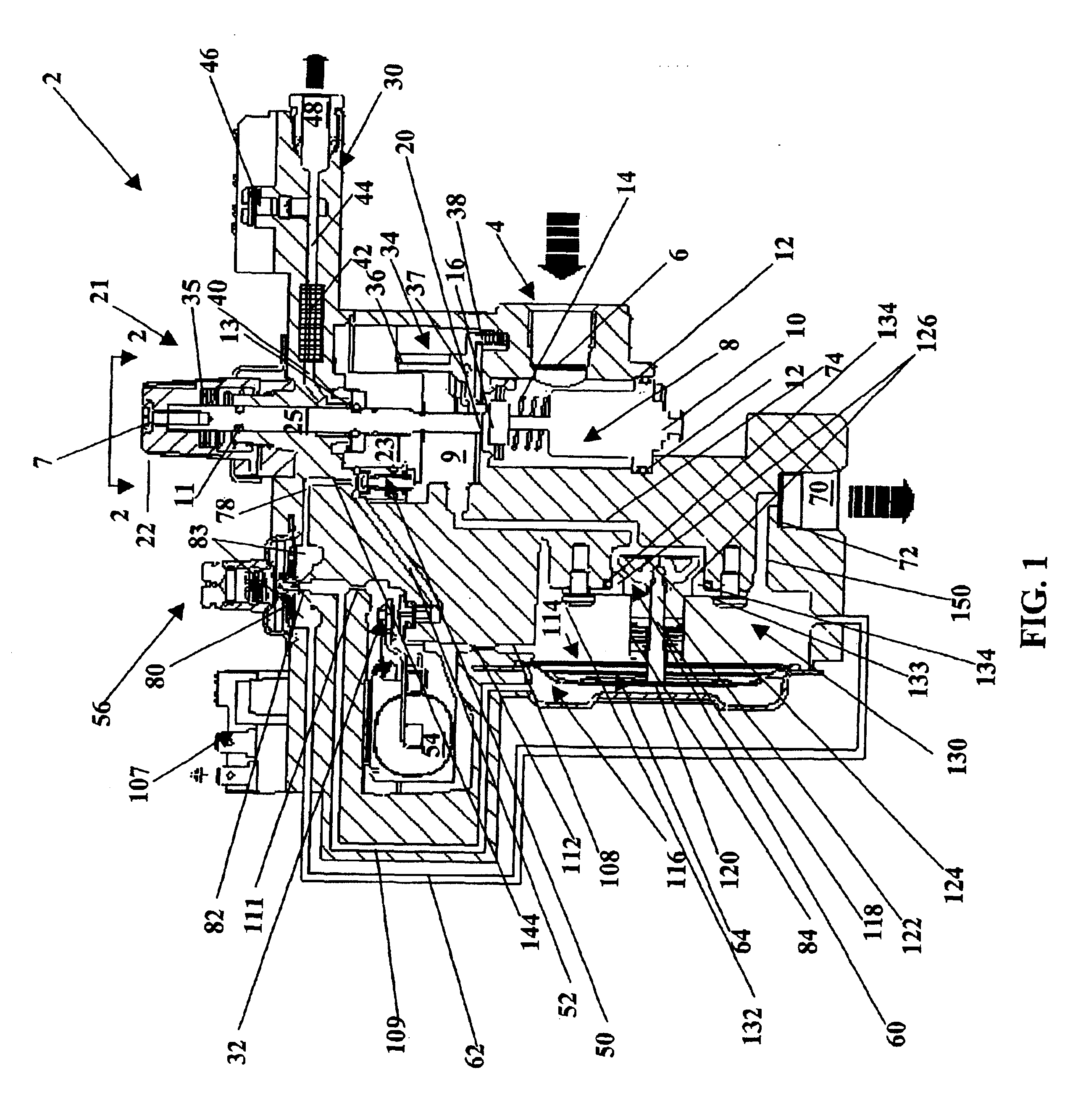
[0037]When the control valve 50 is closed, a significant advantage to the present invention is the ability to release fuel, e.g., gas pressure as soon as possible and not allow it to build up within the main control device 2. The pressure on first side 116 of the diaphragm 64 of the main valve 60 is allowed to bleed off through a seventh fluid line 78, having a tertiary bleed orifice 144, through the manual valve 50 through the seventh fluid line 78 as well as through the third fluid line 62 into the outlet chamber 130 and then through the outlet 70. Fuel is also quickly released from the actuator valve 32 to the second side 114 of the diaphragm 64 for the main valve 60 through the secondary bleed orifice 112 to outlet 70 to close the main valve 60.

Problems solved by technology

Unfortunately, it is not always known what type of fuel will be available.
Initially, natural gas may not be available because underground gas lines are not in place in the area, or because hook up to natural gas lines is delayed by frozen ground, or for other reasons.
This can be a very expensive and time-consuming conversion.
Also, some gas-powered devices, e.g., furnaces, hot water heaters, and so forth are built without knowing the preferences of the ultimate consumer.

Method used


Image

  • Convertible control device capable of regulating fluid pressure for multiple fluid types and associated method of use
  • Convertible control device capable of regulating fluid pressure for multiple fluid types and associated method of use
  • Convertible control device capable of regulating fluid pressure for multiple fluid types and associated method of use

Examples


Embodiment Construction

[0021]In the following detailed description, numerous specific details are set forth in order to provide a thorough understanding of the invention. However, it will be understood by those skilled in the art that the present invention may be practiced without these specific details. In other instances, well-known methods, procedures and components have not been described in detail so as to obscure the present invention. For example, the invention can be applied to virtually any type of gas-powered device that can be powered by natural gas and liquefied petroleum. Therefore, this invention can be applied to virtually any type of gas appliance including, but not limited to, furnaces, heaters, fireplaces, and so forth. In addition, this invention may be applied to an engine. The fuel is preferably, but not necessarily, gas. Illustrative, but nonlimiting examples of the types of gas utilized with the present invention include natural gas, manufactured gas and liquefied petroleum, e.g., l...


PUM


Abstract

A pressure control device and associated method of use capable of regulating fluid pressure for multiple fluid types. The pressure control device includes a fluid sensing port, a pressure responsive device, a fluid sensing port, a valve, a valve seat, a first valve chamber, a second valve chamber that is moveable in relationship to the first valve chamber, a first member located within the first valve chamber, a first biasing mechanism located between the pressure responsive device and the first member, a first adjustment mechanism adjustably attached to the first valve chamber for selectively positioning the first member in relation to the first valve chamber, a second member located within the second valve chamber, a second biasing mechanism to apply pressure to the second member and a second adjustment mechanism adjustably attached to the second valve chamber for selectively positioning the second member in relation to the second valve chamber.

Description

BACKGROUND OF THE INVENTION[0001]In the past, there has been a desire to utilize more, than one type of fluid that is utilized as fuel for virtually any type of gas-powered devices including, but not limited to, furnaces, heaters, fireplaces, engines, and so forth.[0002]Typically, most gas-powered devices require some type of regulation of the gas pressure. Two types of common fluids used as fuels include liquefied petroleum, e.g., liquid propane, and natural gas. There are major differences between these two fuels since they are supplied to the gas-powered devices at different pressures and they have different burning characteristics. For example, in a furnace or burner application, the typical pressure value for natural gas is 3.5 inches H2O while the typical pressure value for liquefied petroleum is 10.0 inches H2O. Therefore, a pressure regulator for a gas-powered device must regulate to a lower pressure for natural gas than for higher pressure than for liquefied petroleum.[0003...

Claims


Application Information

Patent Timeline
Patent Type & Authority Patents(United States)
IPC IPC(8): F02M13/08F02M21/06F02M13/00F02M21/02G05D16/06G05D16/04
CPCF02M13/08F02M21/06G05D16/0661F02M21/0239F02M21/0233Y02T10/32F02M21/0212F02M21/0215F02M21/0242F02D19/027Y02T10/30Y10T137/0318Y10T137/1516Y10T137/5109Y10T137/7836
Inventor HADDAD, NABIL MIKHAEL
Owner ROBERTSHAW CONTROLS CO
Why Eureka
Try Eureka